seat Workshop Repair Guides

SEAT Workshop Service and Repair Manuals

Air filter: component overview > < Engine control unit
Removing and installing intake manifold
t  Removing → Anchor
t  Fitting → Anchor
   
Consult the equivalence table for tools and equipment according to applicability among Seat / VW / Audi / Skoda → Chapter.
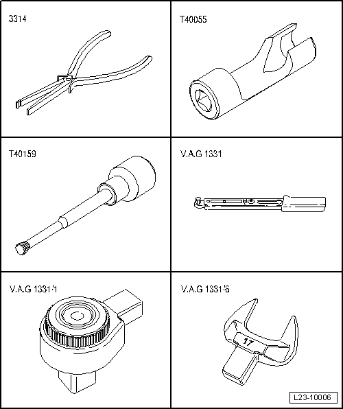
Special tools and workshop equipment required
t  Base -3314-, see equivalent → Anchor
t  Socket wrench insert -T40055-, see equivalent → Anchor
t  Wrench XZN 8 -T40159-, see equivalent → Anchor
t  Torque wrench -VAG 1331-, see equivalent → Anchor.
t  Ratchet 1/2' x 9-12 -VAG 1331/1-, see equivalent → Anchor
t  Torque wrench insert -VAG 1331/6-, see equivalent → Anchor

Removing
  WARNING
t  Always read rules for cleanliness and instructions for working on fuel system → Chapter.
t  Always follow these rules for cleanliness and instructions before starting work and while working on the fuel system.
   
–  Loosen the engine cover at the locations -arrows- and remove.
  E10-10087
–  Unscrew the securing bolts -arrows- and remove the engine soundproofing..
  E10-0086
–  Loosen the angled bracket -1- and -2- and remove the right hose from the charged air cooler.
  A21-10489
–  Remove bolts -arrows-.
–  Free coolant hose -3-.
–  Release the hose clamp -2-.
–  Unplug electrical connector -1- at charge air pressure sender -G31-/charge air pressure sender -G42- and remove the right air intake pipe.
–  Detach the electrical connectors on the glow plugs → Chapter.
  Caution
Pay particular attention not to damage the wires when removing the connections, because otherwise it would be necessary to replace the entire wiring harness. Do not press pliers -3314- together excessively when removing the connection, because otherwise the bearing supports could be damaged.
  A21-10435
–  Remove exhaust gas recirculation cooler changeover valve -N345--left arrow- from bracket and lay aside.
  N23-10289
–  Unscrew bolts -2-, place coolant return line to one side.
  A19-10991
–  Unscrew bolts -arrows-, lay coolant return line aside.
  N23-10326
–  Unscrew bolt -2- and union nuts -1, 3-; remove high-pressure line.
  A23-10449
–  Unscrew the union nuts -1- for high-pressure pipes on injectors using socket insert -T40055-.
–  Unscrew the union nuts for high pressure pipes on fuel rail with the open-ended pin tool -VAG 1331/6-.
–  Place the removed high-pressure lines on a clean cloth.
  A23-10451
–  Remove the fuel rail, unscrewing the two bolts -arrows-.
  A23-10451
–  Disconnect electrical connection -2- on throttle valve control unit -J338-.
–  Remove bolt -1- for dipstick guide tube.
  A23-10448
–  Unscrew the support flange -1- and the bolts -2- from the connecting pipe of the exhaust gas recirculation and and remove the pipe.
  A26-10901
–  Remove the fixing bolts of the intake manifold -arrows- in diagonal sequence starting from outside and working inwards using socket XZN 8 -T40159-.
–  Remove the intake manifold.
Fitting
Carry out the assembly operations in reverse order to those described for the disassembly, taking the following into account:
l  Specified torque → Chapter „Assembly overview - intake manifold with attachments“.
–  Renew the seals.
–  Tighten the fastening bolts of the intake manifold crosswise from the outside to the inside.
–  Install air pipe at the front → Chapter.
–  Fit the centre sound proofing → Exterior body installation work; Rep. gr.50 .
  A23-10450

Air filter: component overview > < Engine control unit