Leon Mk1
| Assembly overview - oil pump, sump, balancer shaft module |

| 1 - | Balancer shaft assembly |
| q | Remove balancer shaft module → Chapter |
| q | Install balancer shaft module → Chapter |
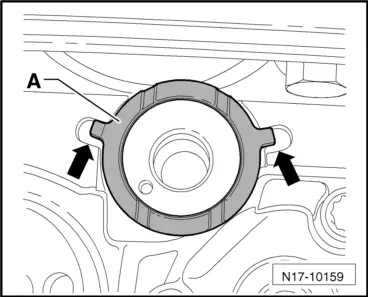
| q | Before installing, check that the two dowel sleeves for centring balancer shaft module on cylinder block are fitted. |
| 2 - | M7 = 13 Nm + 90° (1/4 turn) further; M8 = 20 Nm + 90° (1/4 turn) further |
| q | Renew |
| q | Observe tightening sequence → Chapter |
| 3 - | Oil extraction pipe |
| 4 - | 10 Nm |
| 5 - | 15 Nm |
| q | Loosen and tighten with T-bar and socket, 10 mm -3185- |
| q | Remove using hexagon key extension, 5 mm -3249-. |
| 6 - | Sump |
| q | Clean sealing surface before fitting. |
| q | Install with silicone sealant -D 176 404 A2-. |
| q | Removing and installing → Chapter. |
| 7 - | 20 Nm |
| 8 - | Bracket |
| q | For charge air pipe between exhaust turbocharger and charge air cooler |
| 9 - | 10 Nm |
| 10 - | Oil level and oil temperature sender -G266- |
| 11 - | Seal |
| q | Renew |
| q | Oil before installing. |
| 12 - | Oil drain plug, 30 Nm |
| q | Renew plug with attached seal. |
| 13 - | Seal |
| q | Fitted firmly |
| q | If leaking, nip open and replace |
| 14 - | Connector |
| q | Black, 3-pin |
| 15 - | Bracket |
| q | For oil level/temperature sender wiring harness. |
| 16 - | 25 Nm |
| 17 - | 10 Nm |
| 18 - | 10 Nm |
| 19 - | Intake connecting pipe |
| q | Clean strainer if soiled |
| 20 - | 10 Nm |
| 21 - | O-ring |
| q | Renew |
| 22 - | Oil pump |
| q | Removing and installing → Chapter. |
| q | Before installing, check that the two dowel sleeves for centring oil pump on balancer shaft module are fitted. |
| 23 - | Oil pump drive shaft |
| 24 - | Circlip |
| q | Must lie in base of groove. |
| q | Renew damaged or over-tensioned circlip. |
| 25 - | Spur gear for balancer shaft |
| 26 - | 20 Nm + 90° (1/4 turn) further |
| q | Renew |
| 27 - | Hub |
| q | For intermediate gear wheel. |
| q | Renew |
| 28 - | 90 Nm + 90° (1/4 turn) further |
| q | Renew |
| 29 - | Thrust washer |
| q | For intermediate gear wheel. |
| 30 - | Intermediate gear wheel |
| q | Renew |
| q | A coating is applied to the new intermediate gear wheel which sets the correct tooth backlash through wear. |
| q | When intermediate gear wheels are coated to areas around the circumference, a white spot is fitted to ensure correct installation position. |
| q | The intermediate gear wheel without white spot is fully coated around the circumference |
 Caution
|
| q | Installation position: Part number must be visible |
| q | Installing → Chapter. |
| q | Installing → Chapter. |
| 31 - | Thrust washer |
| q | For intermediate gear wheel. |
| q | Renew |
| q | Note installation position → Fig. |
| q | When installing intermediate gear wheel, secure to housing with grease, if necessary |
| 32 - | Crankshaft sprocket |
| 33 - | Dipstick guide |
| q | For oil dipstick. |
| q | Lugs on dipstick and dipstick guide must align. |
| q | Pull out to extract oil. |
| q | The oil level must not be above the max. mark! |
| q | Checking oil level → Chapter |