seat Workshop Repair Guides

SEAT Workshop Service and Repair Manuals

Exhaust system > < Removing and installing engine control unit
Removing and installing unit injector
   
Removing and installing unit injector
Special tools and workshop equipment required
t  Universal dial gauge bracket -VW 387-
t  Special wrench, long reach -3410-
t  Special wrench, long reach -T10054-
t  Puller -T10055-
t  Torque wrench (5...50 Nm) -V.A.G 1331-
t  Dial gauge

Removing
–  Remove upper toothed belt guard.
–  Remove cylinder head cover → Chapter.
–  Turn crankshaft until the cam pair point evenly upwards for the unit injector which is to be removed.
   
–  Loosen lock nut of adjustment screw -1- and screw the screw out until the relevant rocker arm lies against the plunger spring of the unit injector.
–  Remove rocker arm securing bolts -2- (from outwards to inwards) with socket -3410- and take rocker arm shaft off.
–  Loosen tensioning block securing bolt -3- using special wrench, long reach -T10054- and remove tensioning block.
–  Lever connector off unit injector with a screwdriver. Support opposite side of connector using light finger pressure to prevent canting.
Observe unit injector cylinder allocation.
  N23-0310
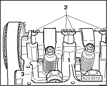
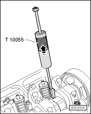
–  Seat the puller into the slot on the side of the unit injector instead of the tensioning block.
–  Pull unit injector out of cylinder head seat with gentle taps.
Installing
  Note
t  
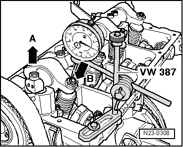
Each time work is performed which requires adjustment of the unit injector, the adjustment screw in the rocker arm and also the unit injector ball stud must be renewed.
t  New unit injectors are supplied with O-rings and heat shield seal.
–  Heat shield seal and O-rings must be renewed if old unit injector is reused → Chapter.
–  Before installing unit injector, check that the three O-rings, the heat shield seal and securing clip are seated correctly.
  Note
The O-rings must not be twisted.
–  Oil the O-rings and fit the unit injector into the cylinder head extremely carefully.
–  Push the unit injector evenly into the cylinder head onto its limit stop.
–  Insert the clamping block in the slot on the side of the unit injector.
  Note
If the unit injector is not at right angles to the tensioning block the securing bolt may loosen and this can damage the unit injector or the cylinder head.
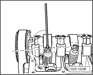
–  Therefore align the unit injector as follows.
–  Screw the new securing bolt into the tensioning block only so far that the unit injector can still be turned easily.
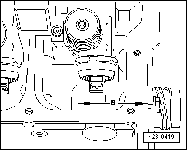
–  Now align unit injector at right angles to camshaft mounting brackets.
  N23-0319
–  Check dimension “a” from outer edge of cylinder head to rounded edge of unit injector with a vernier gauge (measuring range at least 400 mm.)
  N23-0419
CylinderDimension “a”
1333.0 ± 0.8 mm
2245.0 ± 0.8 mm
3153.6 ± 0.8 mm
465.6 ± 0.8 mm

–  If necessary, adjust the unit injector and tighten the securing bolt as follows:
–  Tighten securing bolt to 12 Nm and turn 270° (3/4 turn) further (turning further can be done in several stages).
   
–  Fit rocker arm shaft and tighten new securing bolts as follows:
–  First tighten inner bolts -2- then outer bolts -1- by hand. Then using same sequence, tighten to 20 Nm and turn 90° (1/4 turn) further.
  A15-0531
–  Fit the dial gauge onto the adjustment screw of the unit injector as shown.
–  Turn the crankshaft in engine direction of rotation until the roller of the rocker arm is positioned on the peak of the drive cam. Roller side -arrow A- positioned at highest point, dial gauge -arrow B- positioned at lowest point.
–  Remove dial gauge.
–  Now turn adjustment screw into rocker arm until a firm resistance is felt (unit injector positioned at stop).
  N23-0308
–  Turn adjuster screw 180° back off stop.
–  Hold adjuster screw in this position and tighten lock nut to 30 Nm.
–  Connect unit injector connector.
–  Install cylinder head cover → Chapter.
  N23-10092

Exhaust system > < Removing and installing engine control unit