
Leon Mk1
|

| 1 - | Half bearings 1 and 4 |
| q | For bearing cap without oil groove. |
| q | For cylinder block with oil groove. |
| q | Do not interchange used bearing shells (mark). |
| 2 - | 65 Nm + 90° (1/4 turn) |
| q | 10 pieces |
| q | replace |
| q | For the measure of radial play, tighten to 65 Nm but not more |
| 3 - | Bearing caps |
| q | Bearing cap 1: Pulley side: |
| q | Bearing cap 3 with rebates for the thrust washer |
| q | Bearing shell retaining lugs on cylinder block and bearing caps must align. |
| 4 - | Half-bearing |
| q | For bearing cap without oil groove. |
| q | For cylinder block with oil groove. |
| 5 - | Attack washer |
| q | For bearing cap 3 |
| q | Note attachment |
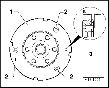
| 6 - | Generator wheel: |
| q | Only for engine codes ASZ, ATD, BPX, BLT, BUK, AXR |
| q | For engine speed sender -G28- |
| q | If this is damaged, replace it |
| q | Always renew sender wheel if bolts have been loosened |
| q | removing and fitting → Fig. |
| 7 - | 10 Nm + 90° (1/4 turn) |
| q | Only for engine codes ASZ, ATD, BPX, BLT, BUK, AXR |
| q | 3x |
| q | replace |
| q | Always renew sender wheel if bolts have been loosened |
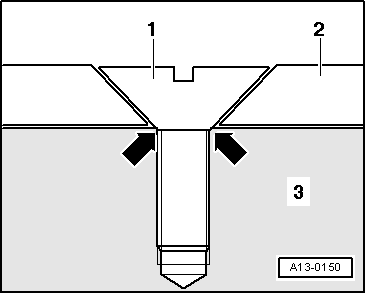
| 8 - | Dowel pin |
| q | Only for engine codes ASZ, ATD, BPX, BLT, BUK, AXR |
| q | Check the extension of the pin over the crankshaft → Fig. |
| 9 - | Crankshaft |
| q | New axial play: 0.17 mm Wear limit: 0.37 mm |
| q | Check radial clearance with Plastigage. New: 0.08 mm Wear limit: 0.17 mm |
| q | When measuring the radial play, do not rotate the crankshaft |
| q | Crankshaft dimensions → Chapter |
| 10 - | Attack washer |
| q | For cylinder block, bearing 3 |
 Note
Note
|
|