seat Workshop Repair Guides

SEAT Workshop Service and Repair Manuals

Servicing valve gear > < Removing and installing cylinder head
Removing and installing intake manifold (top section)
t  Removing → Anchor
t  Installing → Anchor
t  Tightening torques → Anchor
   
Consult the equivalence table for tools and equipment according to applicability among Seat / VW / Audi / Skoda → Chapter.
Special tools and workshop equipment required
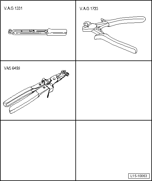
t  Torque wrench -VAG 1331-, see equivalent → Anchor.
t  Pliers for CLOC hose clips -VAG 1723-, see equivalent → Anchor
t  Pliers for spring-loaded band-type clamps -VAS 6499-, see equivalent → Anchor

Removing
  Note
t  All cable ties which were opened or cut during removal must be renewed at the same points.
t  Disconnect battery earth cable only with ignition switched off. On vehicles with coded radio, obtain and observe the anti-theft coding.
t  After disconnecting, the following work is necessary depending on the vehicle equipment: Code radio, set clock, synchronise power window motors.
  Caution
Follow steps required when disconnecting battery → Electrical system; Rep. gr.27.
   
–  With ignition switched off, disconnect earth wire -arrow- at battery.
  E27-10033
–  Detach vent hose -2- leading to exhaust gas recirculation valve -N18-.
–  Remove hose -4- for oil pan ventilation from air pipe.
–  Remove air pipe from clamps -1- and -3-.
  A10-10330
–  Unscrew bolts -arrows-.for coolant expansion reservoir.
–  Disconnect connector for insufficient coolant indicator switch -F66- at bottom of coolant expansion reservoir and place to side with coolant hoses -1- and -2- connected.
  A19-10068
–  Separate pipe -1- from hose on oil pan.
–  Separate vacuum line -2- to power brake servo-unit on firewall.
  A15-10169
–  Unscrew bolts -Arrows- for throttle valve control unit -J338- from intake manifold.
  Note
Shown in illustration with engine removed.
  A15-1058
–  Disconnect connector -1-.
–  Remove nuts -arrows-.
  Note
Disregard -items 2 ... 4-.
  A15-1056
–  Unscrew securing bolts for fuel rail -arrows-.
–  Pull fuel rail off intake manifold together with injectors and set it down on a clean cloth at rear of engine compartment.
  Note
Disregard -items 1 ... 3-.
  A15-1057
–  Unscrew nuts -arrows-.on upper coolant line.
  Note
Ignore -item 1-.
  A15-1059
–  Loosen the clips at the connections -arrows-. To do this, use CLIC hose clip pliers -VAG 1723-.
–  Pull out oil dipstick.
–  Remove upper section of intake manifold.
  Note
Block off the intake ports of the intake manifold (lower section) with clean cloths.
Installing
Reassembly is carried out in the reverse order; note the following:
  Note
t  Renew gaskets and seals.
t  Secure all screw joints with serial hose clips → Spare parts catalogue.
  A15-1060
–  Slide upper part of intake manifold onto connection hoses and fasten clamps -Arrows- with pliers for CLIC hose clamps -VAG 1723-.
–  Observe measures to be taken after connecting the battery → Electrical system; Rep. gr.27.
Tightening torques
  A15-1060
Components:Nm
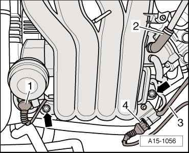
Intake manifold (top section) to support20
Support for intake manifold (top section) to engine20
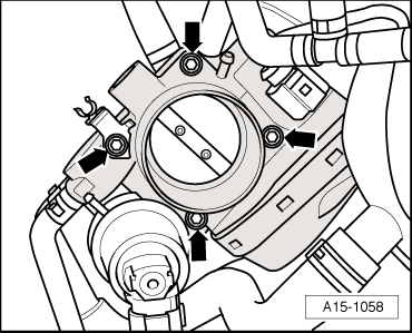
Throttle valve module to intake manifold (top section)10
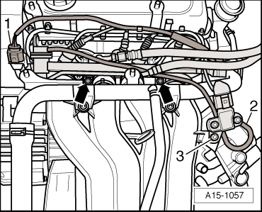
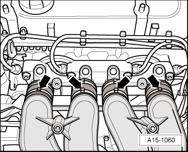
Fuel rail to intake manifold (top section)10
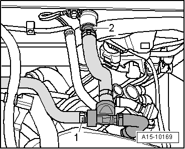
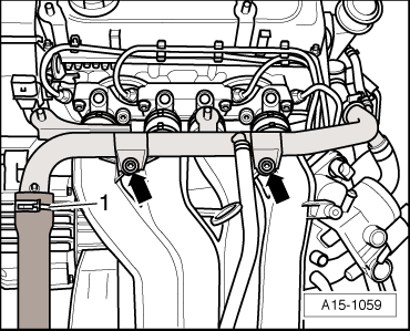
Coolant pipe to intake manifold (top section)10


Servicing valve gear > < Removing and installing cylinder head