seat Workshop Repair Guides

SEAT Workshop Service and Repair Manuals

Charge air cooler > < Checking charge air system
Pressure capsule with charge pressure actuator position senderG581: Renew.
Pressure capsule with charge pressure actuator position sender -G581-: Renew.
Consult the equivalence table for tools and equipment according to applicability among Seat / VW / Audi / Skoda → Chapter.
Special tools and workshop equipment required
   
t  Measuring container -T10422-, see equivalent → Anchor
  W00-10847
t  
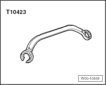
Ring spanner -T10423-, see equivalent → Anchor
t  
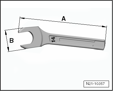
Special wrench, long reach -T40055-
t  Central diagnosis -VAS 5051B-, see equivalent → Anchor or central diagnosis -VAS 5052-, see equivalent → Anchor
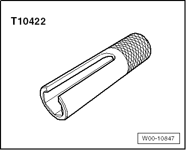
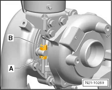
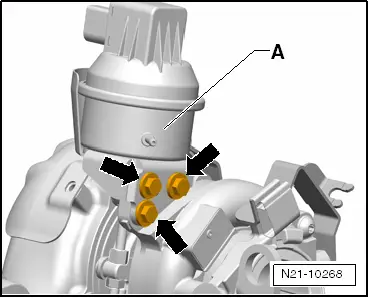
  Caution
The specified special tools, especially the socket -T10422-, are only intended to be used for the following work sequences described and should never be used for other screw connections. Deformation may occur when higher tightening torques are applied.
  Note
There is a spare part set available for replacing the pressure capsule with charge pressure actuator position sender -G581-, → ETKA (Electronic parts catalogue).
Removing
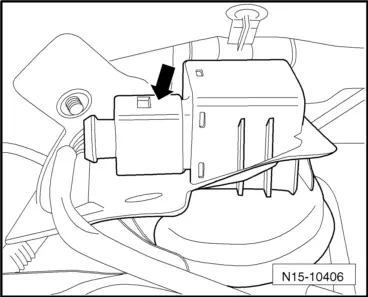
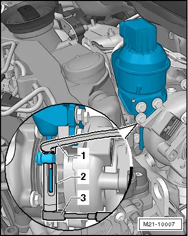
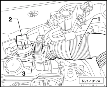
–  Remove air filter housing with air mass meter and connecting pipe → Chapter.
  W00-10838
–  Open the protective mat and unplug the connector -arrow- at the side of the Position sender for charge pressure actuator -G581-.
–  Remove the connecting pipe -1- of the cylinder head cover and cylinder block ventilation; press the release tabs for this purpose.
  N15-10406
–  Free vacuum hoses -arrows-.
  A21-10487
–  Unscrew bolt -2- (captive), swing air pipe with inlet connection to rear and pull off from turbocharger.
–  Seal the opening of the turbocharger using the cover of the spare part set.
–  Remove the vacuum line of the turbocharger.
  A21-10487
–  Unscrew the nut -arrow- for fixing the oil supply line / vacuum line to the cylinder head.
  Caution
You have to hold the connecting support tight when removing the oil supply hose. Risk of further damage.
–  Keep a 14 mm spanner at hand for the purpose as shown.
  N17-10165
14 mm tool for securing the connecting support of the oil supply line
t  A = 110 mm
t  B = 25 mm
  N21-10357
–  Hold the connecting support tight and remove the oil supply line -arrow- of the turbocharger using the socket -T40055-.
–  Seal the opening of the turbocharger oil supply line using the plug of the spare part set.
  N21-10190
–  As shown in the illustration, apply the Ring spanner -T10423--1- and the socket -T10422--2- with the ratchet (switchable)-3-.
  M21-10007
–  Hold the counter nut -B- with the ring spanner -T10423- and remove the fixing nut of the control rod -A- using the socket -T10422-.
  N21-10269
–  Unscrew the securing screws of the pressure capsule -arrows- and remove the pressure capsule -A-.
Installing
  Caution
Then use new nuts and bolts from the spare part kit.
–  If necessary, remove the bottom fixing nut of the control rod of the new pressure capsule.
–  Screw the counter nut in the direction of the pressure capsule onto the control rod to the end by hand.
–  Guide the control rod through the adjusting lever of the turbocharger, position the pressure capsule -A- and pre-tighten the fixing screws.
  N21-10268
–  Tighten securing bolts -arrows- to 8 Nm.
  Note
Make sure that the guide piece slides easily across the control rod.
–  Remove the protective cap, position the oil supply line on the turbocharger and tighten to 22 Nm.
  N21-10268
–  Connect the plug connector -2- to the position sender for charge pressure positioner -G581- and attach the protective mat.
–  Connect vehicle diagnostic tester.
Select operating mode:
–  Touch the pushbutton for the „vehicle self-diagnosis“ on the screen.
Select vehicle system:
–  Press button „01 - Engine electronics“ on display.
The control unit identification and engine control unit coding are indicated on display.
Select diagnostic function:
–  Touch the pushbutton „011 - Measured values“ on the screen.
–  Enter the value block „120“ using the numeric keypad and confirm the value by pressing the „Q“ button.
–  Connect the manual vacuum pump -VAS 6213- to the pressure capsule.
–  Build up a vacuum, set the voltage to 0.760 V and observe the bottom value of the value block in the process.
  Caution
During the subsequent procedure for setting the control rod, the vacuum pressure as well as the voltage of 0.760 V must be kept constant.
  N21-10174
–  Slowly unscrew the counter nut -B- from the control rod (screw from the rod). The adjustment lever is positioned at the lower »stop«.
–  Hold the fixing nut -B- tight and turn the fixing nut -A- on the control rod against the adjustment lever in the process. Tighten slightly using the ring spanner -T10423-.
–  Allow the vacuum to escape from the pressure capsule.
–  Check the bottom value of the value block; the value should be between 3.30 and 3.90 V when depressurised.
–  Position the socket -T10422-, secure the counter nut -B- with the ring spanner -T10423- and tighten the fixing nut -A-.
  Caution
Build up a vacuum of 0.75 ± 0,05 bar in the pressure capsule in order to check whether adjustment lever is seated at the »stop«. The voltage of 0.760 V must be at hand.
  N21-10269
Voltage value in good condition
–  Press the locking mechanism on the control rod by hand and turn by 90° -in the direction of the arrow-.
–  Seal the joint control rod / fixing nut with sealing paint from the spare part set.
  N21-10396
Voltage value is not correct
–  Hold the counter nut -B- tight, undo the fixing nut -A- of the control rod and correct the value by turning the counter nut -B-.
–  Hold the counter nut -B- tight, counterhold the fixing nut -A- and tighten using the socket -T10422-.
  N21-10269
–  Press the locking mechanism on the control rod by hand and turn by 90° -in the direction of the arrow-.
–  Seal the joint control rod / fixing nut with sealing paint from the spare part set.
  N21-10396
Continuation
–  Position the fixing nut -arrow- for connecting the oil supply line / vacuum line to the cylinder head and screw tight.
–  Remove the cover of the turbocharger.
–  Complete the engine.
–  Start the engine and erase the fault memory → Chapter
–  Carry out adjustment as follows:
Select diagnostic function:
–  Touch the pushbutton „006 - Basic setting“ on the screen.
–  Enter the value block „120“ using the numeric keypad and confirm the value by pressing the „Q“ button.
–  Press the button „Activate“ in the bottom half of the screen.
–  Observe the value display in the bottom window of the display; It should deviate between 0.65 ... 0.85 V and 3.30 and 3.90 V (pressure capsule changes between the end stops)
If the values are correct:
–  End basic setting procedure.
  N17-10165

Charge air cooler > < Checking charge air system