seat Workshop Repair Guides

SEAT Workshop Service and Repair Manuals

Intake manifold > < Engine control unit with antitheft protection: Removing and installing.
Engine control unit with antitheft protection: removing and fitting
t  Removing → Anchor.
t  Installing → Anchor.
Special tools and workshop equipment required
   
t  Hot air pistol -1- (of the wire harness repair kit -VAS 1978A-), see equivalent → Anchor
t  Connectable nozzle -2- (also from the cable repair kit -VAS 1978A-)
t  Self-locking pliers, sold commercially (gripping jaws) -3-
t  Central diagnosis -VAS 5051B- o central diagnosis -VAS 5052-
  Note
To replace the engine control unit, connect the central diagnosis -VAS 5051B- or central diagnosis -VAS 5052- and complete the guided function „Replace control unit“.
Removing .
–  Switch off ignition and remove ignition key.
–  Remove the front plate of the plenum chamber → Bodywork exterior fitting work; Rep. gr.50.
  Note
  A24-0475
t  The engine control unit -1- is bolted to a protective casing -2 and 5-. To make it even more difficult to undo the breakaway bolts -3 and 4- on the locking device-2-, a threadlocker has been used.
t  To disconnect connectors on the engine control unit (e.g. when connecting the testing box or to replace the engine control unit), the protective casing must be removed.
–  When renewing engine control unit, select diagnosis object „engine control unit“ in Guided Functions„: replace. “ → Vehicle diagnostic, testing and information system VAS 5051
  A24-0593
–  Open the clip»arrow« and remove the engine control unit.
  WARNING
To ensure that damage (burning) is not caused to the cables and connectors as well as insulation and control units, the following steps must be observed in all cases: Remember the instructions for using the hot-air gun.
Perform settings on hot air blower -4- as shown:
  A24-10451
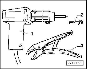
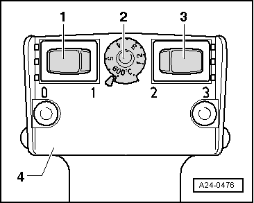
–  Turn temperature settings potentiometer -2- to a maximum heat output of 600 °C.
  Note
t  
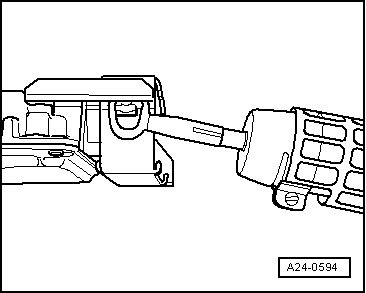
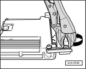
Next, heat the breakaway bolts with the hot-air gun. This reduces the strength of the threadlocker on the thread of the breakaway bolts to make them easier to remove.
t  Cover all painted parts to prevent damage from the hot-air gun or the self-locking pliers.
  WARNING
When breakaway bolts are heated, some parts of the protective casing become very hot. Risk of burn injuries! Also, make sure that, as far as possible, you only heat the breakaway bolt and not adjoining parts. If necessary, cover these parts.
  A24-0476
–  Bring the nozzle of the hot-air gun up to the breakaway bolt on the lock.
–  Connect hot air gun and heat the head bolt approx. 20 to 25 seconds.
  A24-0594
–  Release the breakaway bolts with the self-locking pliers -arrow-.
Follow the same procedure with the second breakaway bolt.
Separate the protective casing from the engine control unit.
–  Unlock the front and rear connectors from the engine control unit.
  A24-0595
Installing .
Installation is carried out in the reverse order; note the following:
–  Remove the remains of the threadlocker from the breakaway bolt holes. A male thread tap can be used for this.
–  First connect the rear connector and next, the front connector to the engine control unit and lock.
–  It is essential that the protective casing -2 and 5- is replaced onto the engine control unit.
–  Use new breakaway bolts.
–  Interrogate and erase fault memory if necessary → Chapter.
  A24-0593

Intake manifold > < Engine control unit with antitheft protection: Removing and installing.