
Leon Mk1
| Valve control: removing and fitting |
 Note
Note| t | Cylinder heads which have cracks between the valve seats or between valve seat inserts and the spark plug thread can be used further without reducing service life, provided the cracks do not exceed a maximum of 0.3 mm in width, or when no more than the first four spark plug threads are cracked. |
| t | The engine is not to be started for approx. 30 minutes after installing camshafts, The hydraulic valve compensation parts have to settle (otherwise valves will rest on pistons). |
| t | After working on the valve gear, turn the engine carefully at least two turns to ensure that no valve will be stuck when the engine is started. |
| t | Always replace seals and gaskets. |
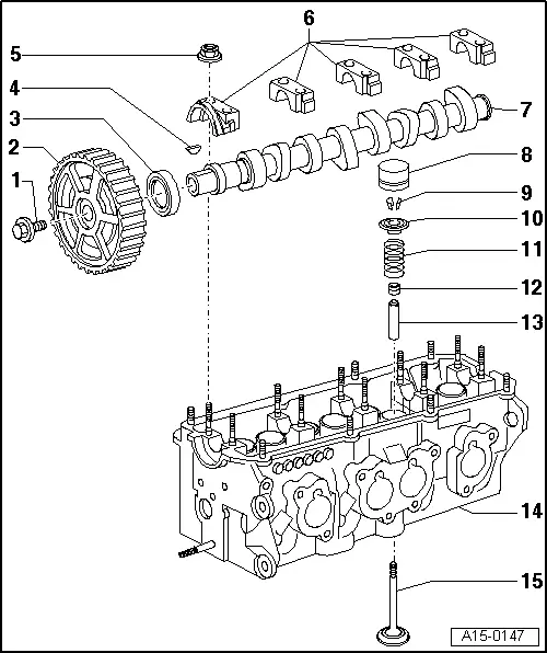
| 1 - | 100 Nm |
| q | Use counterhold -T20018B- to loosen and tighten |
| 2 - | Camshaft sprocket |
| q | Using the scraper ring for the Hall sender -G40- |
| 3 - | Camshaft oil seal: |
| q | Do not oil sealing lip of oil seal |
| q | Renew → Chapter |
| 4 - | Woodruff key |
| q | Check for firm attachment |
| q | Check correct seating |
| 5 - | 20 Nm |
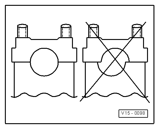
| 6 - | Bearing cap |
| q | Note installation position → Fig. |
| q | Apply a small amount of sealant -D 454 300 A2- to the touching surface before fitting |
| 7 - | Camshaft |
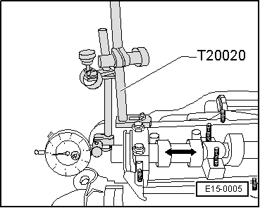
| q | Check axial clearance → Fig. |
| q | Removing and installing → Chapter |
| q | Check radial clearance with Plastigage, wear limit: 0.1 mm |
| q | Off centre: max. 0.05 mm |
| 8 - | Hydraulic tappet |
| q | Do not mix them up |
| q | With hydraulic valve clearance compensation. |
| q | Testing → Chapter |
| q | Set down with cam bearing surface facing downwards. |
| q | Oil contact surface |
| 9 - | Semicones |
| 10 - | Valve plate spring |
| 11 - | Valve spring |
| q | Removing and installing: |
| q | Cylinder head fitted → Chapter |
| q | Cylinder head removed: using pressure tool -T20034D- |
| 12 - | Valve stem seals: |
| q | Renew → Chapter |
| 13 - | Valve guide |
| q | Testing → Chapter |
| q | Renew → Chapter |
| 14 - | Cylinder head |
| q | Removing and installing → Chapter |
| q | Reworking valve seats → Chapter |
| q | Check the valve guides → Chapter |
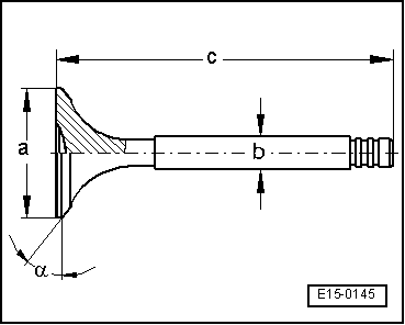
| 15 - | Valve |
| q | Not to be reworked; only grinding-in permissible |
| q | Valve dimensions → Fig. |
| q | Check the valve guides → Chapter |
| q | Reworking valve seats → Chapter |
|
|
|
|
|
Note
|
|
| Dim. | Inlet valve | Outlet valve | |
| Ø a | mm | 39,5 ± 0,15 | 32,9 ± 0,15 |
| Ø b | mm | 6,92 ± 0,02 | 6,92 ± 0,02 |
| c | mm | 91,85 | 91,15 |
| α | ∠° | 45 | 45 |