
Leon Mk1
| Crankshaft: removing and fitting |
 Note
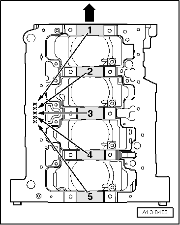
Note| t | The cylinder block will be factory-assigned with the correct thickness of bearing shells. The thickness is identified by coloured spots. |
| t | To perform repairs secure the engine with the support tool -T20172/1, /2, /3,- → Chapter. |
| t | If operations are to be carried out on the crankshaft or on the sealing flange, the engine flywheel and intermediate plate must be removed before attachment to the counterhold -T20172/1, /2, /3,- → Chapter . |
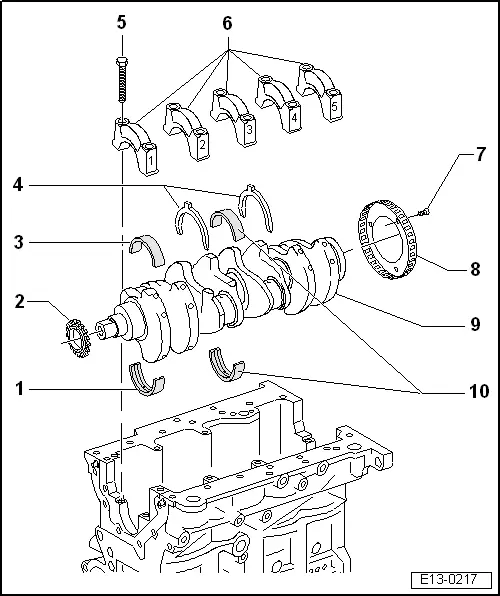
| 1 - | Bearing shells 1, 2, 4 and 5 |
| q | For cylinder block with oil groove. |
| q | Do not exchange used bearing shells (mark). |
| q | New bearing shells must be used that are marked with the correct colour → Fig. |
| 2 - | Drive sprocket |
| q | To drive the oil pump |
| 3 - | Bearing shell |
| q | For bearing cap without oil groove. |
| q | Do not exchange used bearing shells (mark). |
| 4 - | Thrust washer |
| q | For engine block, bearing 3 |
| q | Note attachment |
| 5 - | 65 Nm +1/4 turn (90º) |
| q | Replace |
| q | Tighten to 65 Nm to measure radial play of the crankshaft |
| 6 - | Bearing caps |
| q | Bearing cap 1: timing belt side |
| q | Bearing cap 3: with cut-outs for thrust washers |
| q | Bearing shell retaining lugs (cylinder block/bearing cap) must be on the same side. |
| 7 - | 10 Nm +1/4 turn (90º) |
| q | Replace |
| q | Whenever the bolts are loosened, the sender wheel should be replaced → Fig. |
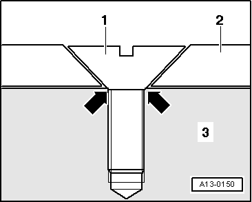
| 8 - | Sender wheel |
| q | For engine speed sender -G28- |
| q | Can only be fitted in one position (the holes are offset) |
| q | Whenever the bolts are loosened, the sender wheel should be replaced |
| q | Removing and installing → Fig. |
| 9 - | Crankshaft |
| q | Axial play: |
| q | New: 0.07 … 0.23 mm |
| q | Wear limit: 0.30 mm |
| q | Measure the radial play with Plastigage |
| q | New: 0.02 … 0.04 mm |
| q | Wear limit: 0.15 mm |
| q | When measuring the radial play, do not rotate the crankshaft |
| q | Crankshaft dimensions → Chapter |
| 10 - | Bearing shell 3 |
| q | For cylinder block with oil groove. |
| q | For bearing cap without oil groove. |
| q | Do not exchange used bearing shells (mark). |
| q | New bearing shells must be used that are marked with the correct colour → Fig. |
|
|
| Letters on the engine block | Colour of bearing shell | |
| S | = | black |
| R | = | red |
| G | = | yellow |
Note
|