seat Workshop Repair Guides

SEAT Workshop Service and Repair Manuals

Checking charge pressure regulating valve vacuum unit > < Checking charge pressure control solenoid valve N75
Checking charge air pressure senderG31
   
Checking charge air pressure sender -G31-
Special tools and workshop equipment required
t  Hand multimeter -V.A.G 1526 A- or hand multimeter -V.A.G 1526C-
t  Auxiliary measuring set -V.A.G 1594 A- or auxiliary measuring set -V.A.G 1594C-
t  Adapter cable, 121-pin -V.A.G 1598/31-

Not illustrated
t  Current flow diagram
Test prerequisites
l  Self-diagnosis has detected a fault in the charge air pressure sender → Rep. Gr.01.
l  Ignition switched off
Checking voltage supply and wiring to control unit
   
–  Pull 4-pin connector from charge air pressure sender -G31--arrow-.
  N21-0157
–  Connect multimeter for voltage measurement to contacts 1 (earth) and 3 (positive) of charge air pressure sender -G31- connector using auxiliary cables from auxiliary measuring set -V.A.G 1594 A- or auxiliary measuring set -V.A.G 1594C-.
–  Switch on ignition. Specification: at least 4.5 V
–  Switch off ignition.
If no voltage is present:
–  First check whether a coded radio is fitted. If so, obtain anti-theft coding.
–  Remove battery.
  N21-0159
–  Connect adapter cable, 121-pin -V.A.G 1598/31- to control unit wiring harness. The engine control unit remains disconnected.
  N24-1200
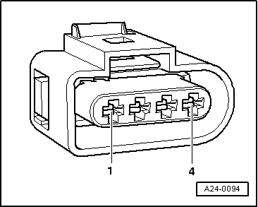
–  Check cables between test box and 4-pin connector for open circuit according to current flow diagram.
Contact 1 and test box socket 108
Contact 3 and test box socket 98
Contact 4 and test box socket 101
Cable resistance: max. 1.5 Ω.
–  Also check wiring for short to one another, short to vehicle earth and short to battery positive. Specification: ∞ Ω.
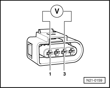
If no cable fault is detected and voltage is present between contacts 1 + 3:
–  Check function → Anchor.
If no cable fault is detected and no voltage is present between contacts 1 + 3:
–  Renew engine control unit → Rep. Gr.24.
Checking function
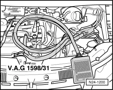
–  Connect adapter cable, 121-pin -V.A.G 1598/31- to engine control unit wiring harness and engine control unit.
–  Connect battery.
  A24-0094
–  Reconnect 4-pin connector to charge air pressure sender -G31--arrow-.
–  Connect multimeter for voltage measurement to sockets 101 (positive) and 108 (earth) using auxiliary cables from auxiliary measuring set -V.A.G 1594 A- or auxiliary measuring set -V.A.G 1594C-.
–  Start engine and measure voltage. Specification: 1.80..2.00 V
–  Start engine and increase to maximum rpm by flooring throttle. Specification: 2.00..3.00 V
If the specifications are not attained:
–  Renew charge air pressure sender -G31- → Item.
–  Interrogate and clear fault memory → Rep. Gr.01
  N21-0157

Checking charge pressure regulating valve vacuum unit > < Checking charge pressure control solenoid valve N75