seat Workshop Repair Guides

SEAT Workshop Service and Repair Manuals

Exhaust system > < Additional signals: checking
Checking process
Checking process
–  Connect fault reader -V.A.G 1551- (-V.A.G 1552-). With ignition turned on select “Address code” 01 to select engine control unit.
   
Indicated on display:
–  Press keys 0 and 8 for the function “Read measured value block” and confirm entry with Q key.
 
Rapid data transfer                 HELP
Select function XX                      
Indicated on display:
–  Press keys 0, 0 and 6 for “Display group number 6” and confirm entry with Q key.
–  Observe figure displayed in display field 2. Specification: 0 0 0
 
Read measured value block               
Enter number group values XXX           
Indicated on display:
–  Depress the clutch pedal. The left-hand digit should change to 1. Specification: 1 0 0
 
Read measured value block      6       →
   0 km/h    0    0    0    0.0 %    255
Indicated on display:
–  Allow clutch pedal to return slowly to its resting position.
The left figure should change again from 1 to 0.
–  Press key.
–  Press keys 0 and 6 for the “End data transfer” function and confirm input with the Q key.
–  Switch off ignition.
If the specification is not obtained:
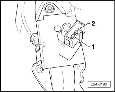
–  Extract the clutch pedal switch Components' fitting locations, → Chapter.
 
Read measured value block      6       →
   0 km/h    1    0    0    0.0 %    255
–  Test resistance in switch's contacts. Specification Without depressing clutch: 1,5 Ω Max. Clutch depressed: ∞ Ω (no continuity)
If the specifications are not attained:
–  Renew clutch pedal switch -F36-.
If the specifications are obtained:
–  Switch on ignition.
  E24-0190
–  Connect multimeter to measure voltage between contact 2 and earth. Specification: at least 11.5 V
If the specifications are not attained:
–  Check wiring between 4-pin connector, contact 2 and fuse 4 for open circuit using current flow diagram for any short circuits. → Current flow diagrams, Electrical fault finding and Fitting locations
If the specification is obtained:
  E24-0191
–  Connect test box -V.A.G 1598/31- to control unit wiring harness. The engine control unit remains disconnected.
  E23-0084
–  Check wiring for open circuit between test box and connector using current flow diagram. Contact 3 + socket 66 Wire resistance: 1,5 Ω Max.
–  Additionally check wires for shorts to one another, to vehicle earth or to battery positive. Specification: ∞ Ω
If no wiring fault is detected:
–  Renew engine control unit → Chapter
  E24-0191

Exhaust system > < Additional signals: checking