seat Workshop Repair Guides

SEAT Workshop Service and Repair Manuals

Cylinder head: Removing and installing > < Cylinder head: Removing and installing
Remove
Remove
–  First check whether the vehicle has a coded radio; if so, consult the antitheft code.
–  With the ignition off, disconnect the battery earth strap.
   
–  Remove the camshaft housing cover -arrows-.
–  Open the expansion tank plug to release the cooling system pressure.
–  Drain the coolant → Chapter.
–  Loosen the strip clamps and detach the coolant hoses from the thermostat housing. Detach the hoses from their fastenings to the cylinder head and intake manifold.
  E15-0065
–  Remove the plug -1-.
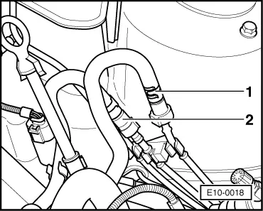
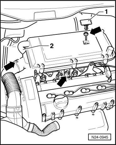
–  Detach the engine oil sump breather hose -2- from the upper air filter element.
–  Detach the hot air intake hose from the hot air pick-up plate.
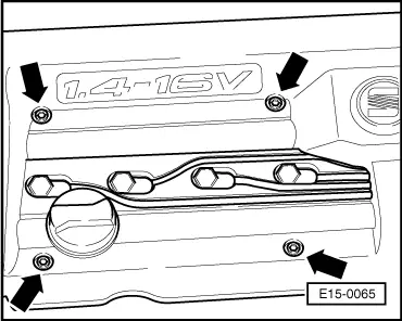
–  Loosen the bolts marked with arrows to remove the air filter.
–  Remove the air filter.
  Note!
t  In production, self-threading screws are used to fix the air filter to the plastic intake manifold and the upper air filter element to the lower element. When loosening or tightening these screws with a screwdriver, the thread of the intake manifold or the lower element of the air filter can be damaged. Thus, when loosening or tightening the screws only use an electric/pneumatic screwdriver following these instructions:
t  maximum revolutions of the screwdriver, 200/min
t  tightening torque maximum 3 Nm
–  Remove the oil dipstick guide sleeve.
  Caution
The fuel supply lines are under pressure. Before loosening the hose connections, place a cloth round the connection. Then eliminate the pressure carefully removing the hose.
  N24-0945
–  Remove the fuel supply and return lines -1- and -2- (depress the lock buttons).
–  Remove the following components from their fastenings and put them to one side:
t  The hose to the activated charcoal filter system from the intake manifold.
t  The vacuum hose to the brake servo, from its fastening to the intake manifold.
t  The three multiple connectors next to the thermostat housing.
t  The connector of the speedometer sender.
Remove the camshaft housing
  Note!
t  On this engine, the camshafts are in a housing. Before removing the housing, remove the main toothed belt.
t  Remove and install the camshafts → Chapter.
Work sequence
–  First remove the two toothed belts → Chapter.
–  Remove the front exhaust pipe from the exhaust manifold.
–  Remove the connector from the lambda probe next to the front engine unit support.
–  Disconnect the sparkplugs and the ignition wiring.
  Note!
When installing, all the wiring holders that are detached or cut when removing the engine must be reinstalled in the same place they were.
  E10-0018
–  Remove the 4-contact connector from the ignition transformer.
–  Remove the 3-contact connector from the Hall sender.
–  Remove the rear toothed belt shield mounting bolt, in the area of the right tow hook ring.
–  Remove the camshaft housing bolts in an inwards cross pattern.
–  Remove the camshaft housing carefully.
–  Remove the rocker arms together with the support elements and place them on a clean surface. Make sure not to swap the rocker arms and the support elements.
Remove the cylinder head
–  Remove fastening clip of the coolant hose to the coolant pump from the thermostat housing.
  N28-0102
–  Loosen the cylinder head bolts in the order indicated and remove them with spanner M12 of the toothed spanner set -U-40020-.
–  Remove the cylinder head carefully.
–  When removing the cylinder head, check that no connector/support is fixed to it; detach any that are.
  Note!
To remove the cylinder head on versions with air conditioning, partially remove the vane pump-alternator-compressor support.
  N15-0026

Cylinder head: Removing and installing > < Cylinder head: Removing and installing