
Leon Mk1
| Piston and connecting rod: disassembly and assembly |
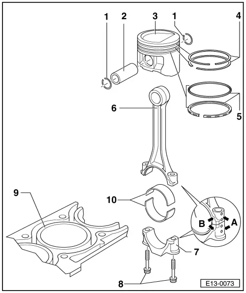
| 1 - | Safety key |
| 2 - | Piston pin |
| q | If difficult to move, heat the piston to 60 oC |
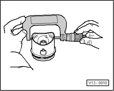
| q | Remove and fit with the -T20019- |
| 3 - | Piston |
| q | Testing → Fig. |
| q | Mark the fitting position and correspondence to the respective cylinder |
| q | The arrow on the piston head should point towards the pulley |
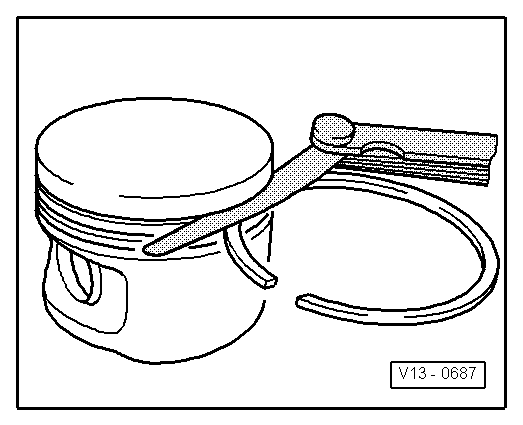
| q | Fit with sleeve for fitting rings |
| 4 - | Compression rings |
| q | Stagger the cuts in 120o |
| q | Remove and fit the rings with ring pliers |
| q | The “TOP” mark must face the piston head |
| q | Check the play between the ends of the rings → Fig. |
| q | Check the coupling play between the rings and the piston grooves → Fig. |
| 5 - | Oil scraper rings |
| q | Carefully remove and fit by hand the two parts of the rings |
| q | The “TOP” mark must face the piston head |
| q | Check the play between the ends of the rings → Fig. |
| q | Check the coupling play between the rings and the piston groove → Fig. |
| 6 - | Connecting rod |
| q | Always replace the unit |
| q | Mark the correspondence to the cylinder -A- |
| q | Fitting position: The marks -B- should point towards the pulley |
| q | Axial guide per piston |
| 7 - | Connecting rod caps |
| q | Check the fitting position |
| q | Cracked connecting rods can be fitted in only one position and only with the corresponding connecting rod |
| 8 - | Connecting rod bolt, 20 Nm + 1/4 turn (90o) |
| q | Replace |
| q | Lubricate the thread and support surface |
| q | Too measure the radial play tighten to 20 Nm, without retightening |
| q | Retightening may be done in several steps |
| q | The retightening angle may be measured with protractor -T20030- |
| 9 - | Aluminium engine block |
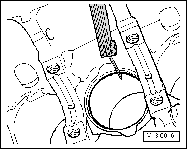
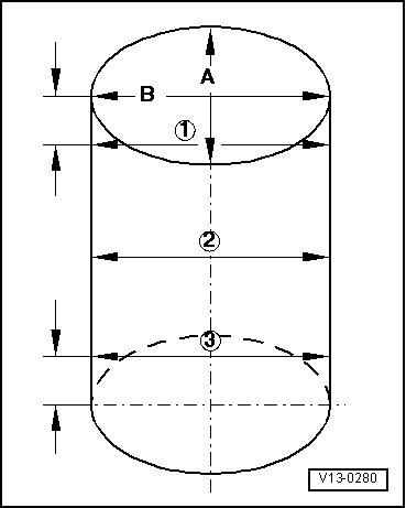
| q | Check the bore of the cylinders → Fig. |
| q | Piston and cylinder dimensions → Chapter |
| 10 - | Half bearing |
| q | Do not swap used half bearings |
| q | Fit the half bearings centred |
| q | Measure the radial play with Plastigage: New: 0.020...0.061 mm Wear limit: 0.091 mm When measuring the radial play do not turn the crankshaft |
|
|
| Piston ring | Wear limit | |
| Compression | 1.0 mm | |
| oil scraper | 1.0 mm | |
|
|
| Piston ring | Wear limit | |
| Compression | 1.5 mm | |
| oil scraper | 1.5 mm | |
|
|
 Note!
Note!
|
|