
Leon Mk1
| Injection system components: removing and installing |
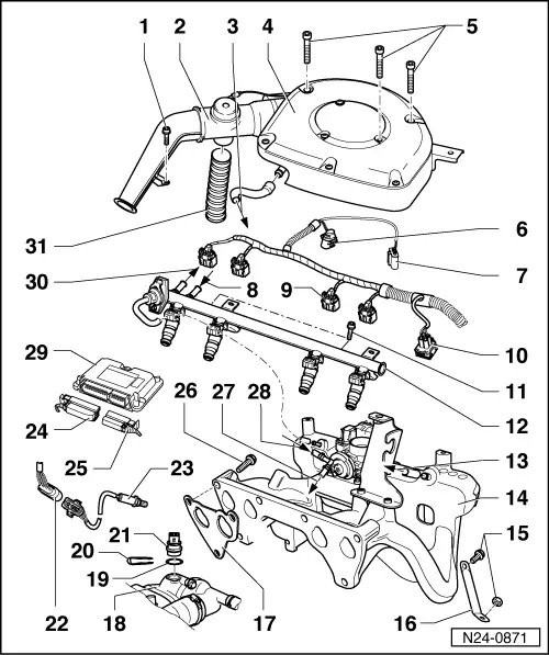
| 1 - | 8 Nm |
| 2 - | Intake duct with regulating flap |
| q | Test intake air preheating → Chapter |
| 3 - | Goes to the cylinder head cover |
| 4 - | Air filter |
| q | Disassembling and assembling → Chapter |
| 5 - | Securing bolts |
| q | For securing the intake manifold, the air filter's upper element and the air filter |
| q | Tightening torque: 3 Nm |
| q | If using an electrical/pneumatic screwdriver: 200/min. max. |
| 6 - | Connector |
| q | 8 contacts |
| q | For butterfly valve control unit -J338- |
| 7 - | Connector |
| q | 4 contacts |
| q | For intake manifold pressure transmitter -G71- with intake air temperature transmitter -G42- |
| 8 - | Comes from the fuel filter |
| q | Secure with clamps |
| 9 - | Connector |
| q | Black, 2 contacts |
| q | For injector -N30-...-N33-) |
| 10 - | Connector |
| q | 4 contacts |
| q | Coolant temperature transmitter -G62- |
| 11 - | 10 Nm |
| 12 - | Fuel distributor with injectors |
| q | Disassembling and assembling → Chapter |
| 13 - | Towards the brake servo |
| 14 - | Intake manifold |
| q | Disassembling and assembling → Chapter |
| 15 - | 20 Nm |
| 16 - | Support |
| q | Between the intake manifold and the engine block |
| 17 - | Joint |
| q | Renew |
| 18 - | Thermostat housing |
| 19 - | O-ring |
| q | Renew if deteriorated |
| 20 - | Staple |
| q | Check firm seating |
| 21 - | Coolant liquid temperature transmitter -G62-* |
| q | With transmitter for coolant liquid temperature indicator -G2- |
| q | Tester → Chapter |
| q | Before removing, reduce the cooling system's pressure |
| 22 - | 4 contact connector |
| q | For Lambda probe and Lambda probe heating |
| q | Contacts 3 and 4, golden |
| q | Location → Anchor, engine compartment's synoptic chart |
| 23 - | Lambda probe -G39-, 50 Nm |
| q | Only grease the threads with -G 052 112 A3-. -G 052 112 A3- must not reach the groove in the body of the probe |
| q | Test the Lambda probe and Lambda regulation → Chapter |
| q | Voltage supply for probe heating through fuel pump relay -J17- |
| q | Test Lambda probe heating → Chapter |
| q | Location → Anchor, engine compartment synoptic chart |
| 24 - | 52 contact connector |
| q | Withdraw or attach the connector with the ignition switched off |
| q | Release in order to withdraw |
| 25 - | 28 contact connector |
| q | Withdraw or attach the connector with the ignition switched off |
| q | Release in order to withdraw |
| 26 - | 25 Nm |
| 27 - | To the cylinder head cover |
| 28 - | It comes from the activated carbon tank electrovalve -N80-*/** |
| 29 - | Engine control unit* |
| (Simos -J361- control unit for injection and ignition system) |
| q | Location: in the water box |
| q | Secured to the support with clips |
| q | Test voltage supply → Chapter |
| q | Renew → Chapter |
| 30 - | It goes towards the fuel supply unit in the tank |
| q | Secure with clamps |
| 31 - | Flexible intake hose |