seat Workshop Repair Guides

SEAT Workshop Service and Repair Manuals

Enginecrankshaft group, pistons > < Assembly mountings
Engine: fitting
Engine: fitting
Tightening torque
  Note
t  Tightening torques apply only to lightly greased, oiled, phosphated or black-finished nuts and bolts.
t  Additional lubricants such as engine or gearbox oil may be used, but do not use lubricants containing graphite.
t  Do not use de-greased parts.
t  Tolerance for tightening torques: ± 15 %.
   
ComponentNm
Bolts/nutsM69
M715
M820
M10:40
M1265

Assembly mountings → Chapter „Assembly mountings: Assembly overview“
  WARNING
Important information for using an engine with one of the designated spare parts (replacement engine):
t  Take note that the roller tappet is not included in the scope of supply of the new replacement engine.
t  When exchanging the replacement engine, the roller tappet has to be used, if this is possible.
t  The following parts will be influenced if the roller tappet is not installed: Camshaft, high-pressure pump and cylinder head cover.
t  The cylinder head may also be influenced as a result of damage to the bolt of the high-pressure pump.
t  The engine will be damaged permanently if the valves make contact with the piston.
Operation process
Installation is carried out in reverse order, noting the following:
  Note
t  When fitting, replace the self-locking nuts and bolts.
t  Renew bolts which have a specified tightening angle, as well as seals and gaskets.
t  Secure all hose connections with the correct hose clips (same as original equipment) → Parts catalogue.
t  Clean input shaft splines and, for used clutch plates, hub splines; remove corrosion and apply a thin coat of grease → Parts Catalogue to the splines. Then move the clutch plate on the input shaft from side to side, until the hub moves smoothly on the shaft. Excess grease must be removed.
For vehicles with automatic Gearbox
–  Install the engine / gearbox assembly with mounted particulate filter.
Continued for all vehicles
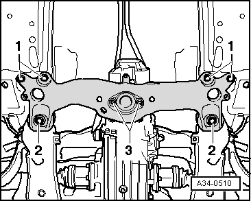
–  Lower engine and gearbox and simultaneously guide stud bolt on left mount into console. Then install the left mount.
  Note
Use vehicle jack to align engine/transmission unit and position in rear area of transmission.
   
–  Position the fastening sleeves -2- of the engine mounting correctly.
–  Tighten the attachment nuts -1- for the engine bracket by hand. For this purpose, the engine must have been aligned in the correct position before tightening.
For vehicles with manual gearbox
–  Mount the clutch slave cylinder → Rep. gr.30.
  Note
  A10-0088
t  Replace the fastening bolt; tightening torque: 23 Nm.
t  The clutch slave cylinder must be pre-tensioned till the securing bolt can be set easily.
t  Before fitting the clutch slave cylinder into the gearbox housing, lithium grease must be applied in the area -a- of the sleeve → Spare parts catalogue.
t  Apply a thin coat of copper grease to the contact surface for the tappet on the clutch release lever → Spare parts catalogue.
–  Install the gear selection mechanism → Rep. gr.34.
For vehicles with automatic Gearbox
–  Install the ATF pipes as well as the ATF filter of the automatic gearbox → Rep. gr.37
  A30-0037
–  Press the selector shaft lever -A- towards the rear as far as it will go -arrow- until parking lock engages.
  Note
Ignore position -B-.
  Note
t  Do not bend the selector shaft lever when pressing on the selector lever cable, as it will otherwise no longer be possible to precisely adjust the gearbox.
t  Do not bend or twist the selector lever cable.
t  Before fitting, lubricate the ball socket of the selector lever cable with polycarbamide grease. For correct version, refer to → Electronic spare parts catalogue.
  A37-0410
–  Press in the ball socket of the selector lever cable -1- to the lever of the selector shaft.
–  Tighten the screws -2- that are used to secure the bracket for the selector lever cable on the gearbox to 23 Nm.
Continued for all vehicles
–  Install the starter electric connectors → Rep. gr.27.
  Note
  E37-10047
When tightening the nut -2- , ensure that the electrical wires are laid out correctly.
Replace nuts and bolts (crossmember on tunnel).
  A27-10038
–  Position tunnel crossmember on gearbox and tighten the new nuts -3- to the specified tightening torque of 23 Nm.
–  Using an engine and gearbox jack -VAG 1383A-, lift the gearbox with a wooden block inserted.
–  Screw in the screws -1- of the tunnel cross-member and tighten to 65 Nm.
–  Screw in the screws -2- of the tunnel cross-member and tighten to 110 Nm + 90°.
–  Fix the articulated shaft to the flange shaft of the gearbox → Running gear, shafts and steering; Rep. gr.40.
–  First tighten all bolts on propeller shaft with 15 Nm, then tighten all bolts with specified torques as follows:
l  M8 Bolt: 20 Nm + 180°
l  M10 Bolt: 50 Nm + 45°
–  Before tightening the mountings, position and pivot the engine.
–  Install pressure differential sender -G505- → Chapter.
–  Install air filter → Chapter.
For vehicles with automatic Gearbox
–  Install the exhaust pipe → Chapter.
For vehicles with manual gearbox
–  Install particulate filter → Chapter.
Continued for all vehicles
–  Screw front mounting bolts into vane pump and tighten to 25 Nm.
–  Screw rear mounting bolts into vane pump and tighten to 20 Nm.
–  Screw belt pulley to vane pump and tighten bolts to 25 Nm.
–  Mount the air conditioning compressor to the bracket → Rep. gr.87.
–  Install poly V-belt → Chapter.
–  Install the lock carrier → Rep. gr.50.
–  Install the hydraulic hoses going to the power steering cooling pipes with new frames.
l  Tightening torque → Chapter „Assembly mountings: Assembly overview“
–  Install the front cover of the bumper → Rep. gr.63.
–  Align exhaust system free of stress → Chapter.
–  Install the sound insulations and the wheel housing liners → Rep. gr.66.
–  Fit the supercharger air system hoses and observe the assembly instructions → Chapter.
–  Install the coolant hoses.
–  Electrical connections and routing → Current flow diagrams, Electrical fault finding and Fitting locations.
–  Install engine control unit → Chapter.
–  Follow the measures for disconnecting the battery → Rep. gr.27.
  Caution
Risk of damage to the control unit due to excess voltage!
Do not use a charger as a starter aid!
Checking engine oil level → Chapter.
–  Check fluid level of power steering → Rep. gr.48.
–  Fill up coolant → Chapter.
–  Perform a self-diagnosis of all controllers using the Diagnosis tester -VAS 505X-.
For vehicles with automatic Gearbox
–  Checking and correcting ATF filling level → Rep. gr.37
  A34-0510

Enginecrankshaft group, pistons > < Assembly mountings