seat Workshop Repair Guides

SEAT Workshop Service and Repair Manuals

Valve control > < Removing and installing toothed belt
Removing and installing cylinder head
t  Removing → Anchor
t  Fitting → Anchor
Consult the equivalence table for tools and equipment according to applicability among Seat / VW / Audi / Skoda → Chapter.
   
Special tools and workshop equipment required
t  Guide pins -3070-, see equivalent → Anchor
t  Hose clamp -3359-, see equivalent → Anchor
t  Hose clamp -T10050-, see equivalent → Anchor
t  Hose clamp -T10051-, see equivalent → Anchor
t  Extractor -T10052-, see equivalent → Anchor
t  Socket XZN 10 -T10385-, see equivalent → Anchor

   
t  Torque wrench (5...50 Nm) -V.A.G 1331-, see equivalent → Anchor
t  Torque wrench (40... 200 Nm) -V.A.G 1332-, see equivalent → Anchor
t  Collecting tray -VAS 6208-, see equivalent → Anchor

  Note
t  Before carrying out further work, disconnect battery earth strap. Check whether a coded radio is fitted. Where necessary, check the anti-theft coding first.
t  All the cable fixings that are opened or cut during removal of the cylinder head must be fitted in the same position when reinstalling the engine.
  WARNING
When doing any repair work, especially in the engine compartment, pay attention to the following due to the cramped conditions:
t  
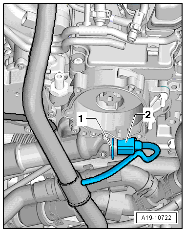
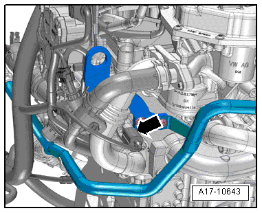
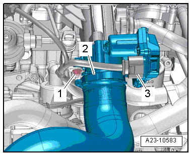
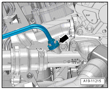
Route all the various lines (e.g. for fuel, hydraulics, active carbon filter system, coolant and refrigerant, brake fluid, vacuum) and electrical wirings in such a way that the original positions are restored.
t  Ensure that there is sufficient clearance to all moving or hot components.
   
Removing
–  Remove engine cover panel -arrows-.
–  Remove air cleaner housing → Chapter.
–  Remove front bumper cover → Rep. gr.63.
–  Move lock carrier to service position → Rep. gr.50.
–  Drain coolant → Chapter.
–  Remove toothed belt → Chapter.
–  Remove coolant pipe (top left) → Chapter.
  E10-10127
–  Disconnect electrical connector -3- at pressure differential sender -G505-.
–  Unscrew screw -2- and move hoses -1- clear from the bracket.
–  Move pressure differential sender -G505- to rear.
  E10-10125
–  Move clear electrical wiring harness -arrow-.
–  Remove nuts -1- and detach bracket -2-.
  A23-10582
–  Remove bolt and nut -arrows-.
–  Release hose clip -3- and detach coolant hose.
–  Press coolant pipe (rear right) to one side.
  Note
-Items 1 and 2- can be disregarded.
  A19-11212
–  Disconnect connector -3-.
–  Remove bolt -1-.
–  Release hose clips -arrows- and disconnect coolant hoses from rear coolant pipe.
–  Move coolant pipe to rear.
  Note
Ignore -item 2-.
  A19-11214
–  Disconnect connector -2- from coolant temperature sensor -G62-.
  Note
Ignore -item 1-.
  A19-10722
–  Unplug electrical connector -arrow- on oil pressure switch -F1-.
  A17-10643
–  Remove bolt -1- for dipstick guide tube.
–  Disconnect electrical connection -3- on throttle valve control unit -J338-.
  Note
Ignore -item 2-.
–  Remove cylinder head cover → Chapter.
  A23-10583
–  Lift retaining clip -arrow- and disconnect coolant line.
  A19-11215
–  Loosen bolt -1- for turbocharger.
  Note
Ignore -item 2-.
  A21-10303
–  Unfasten clamps -2-.
  A26-10538
–  Unscrew bolt -2- from front exhaust pipe
  Note
Ignore -item 1-.
  A26-10120
–  Remove nuts -arrows- for turbocharger.
  Note
Ignore -item 2-.
–  Move clear electrical wiring harness at cylinder head.
  A21-10555
–  Remove bolts -1- and detach camshaft sprocket.
  N15-0232
–  Counterhold using counterhold tool -T10051- and loosen bolt -1- for camshaft hub.
–  Unscrew bolt approx. 2 turns.
  N15-0271
–  Attachpuller -T10052- to cam shaft hub and tighten bolts-1- on hub.
–  Counterhold on hexagon flats (30 mm) of puller and screw in bolt -2- to pull off camshaft hub.
–  Detach hub from taper of camshaft.
  N15-0280
–  Remove bolt -arrow- for toothed belt cover (rear).
  A15-10737
–  Remove bolt for Hall sender -G40--arrow- and move Hall sender -G40- to one side.
  A23-0257
–  Maintain sequence when loosening cylinder head bolts.
  Note
t  A second mechanic is required for removal of the cylinder head.
t  The toothed belt tensioning roller is detached from the stud when the cylinder head is lifted out.
–  Swivel cylinder head towards front and out of rear toothed belt cover and detach tensioning roller at the same time.
–  Take care not to damage the oil return tube for the exhaust gas turbocharger.
–  Take care to place cylinder head down without bending oil return line. If necessary, place a block of wood below exhaust manifold.
  Caution
Risk of damage to glow plugs when putting down cylinder head.
After removal, the cylinder head must not be put down on the gasket side with the glow plugs still installed, because the glow plugs project slightly beyond the gasket surface.
Installing
Reassembly is carried out in the reverse order; note the following:
l  Tightening torque → Chapter „Cylinder head - exploded view“
  Caution
Avoid damage to sealing surfaces.
t  Carefully remove sealant residue from cylinder head and cylinder block.
t  Ensure there are no scratches or scrapes caused.
Avoid damage to cylinder block.
No oil or coolant must be allowed to remain in the blind holes for the cylinder head bolts in the cylinder block.
Risk of leaks at cylinder head gasket.
t  Carefully remove any sealant residue from the cylinder head and cylinder block. Ensure there are no scratches or scrapes caused.
t  Carefully remove any remaining emery and abrasive material.
t  Do not remove new cylinder head gasket from packaging until it is ready to be fitted.
t  Handle the gasket with care to avoid damaging the silicon layer or the ridged area of the cylinder head gasket.
Avoid damage to open valves.
When installing an exchange cylinder head, the plastic protectors fitted to protect the open valves should not be removed until the cylinder head is ready to be fitted.
Avoid damage to valves and piston crowns after working on valve gear.
Turn the crankshaft carefully at least 2 rotations to ensure that none of the valves make contact when the starter is operated.
  Note
t  Renew the bolts tightened with specified tightening angle.
t  Renew self-locking nuts as well as seals, gaskets and O-rings.
t  Cylinder heads for TDI engines must not be reworked.
t  When installing an exchange cylinder head, the contact surfaces between roller rocker fingers and cams must be oiled.
t  Hose connections and air pipes and hoses must be free from oil and grease before fitting.
t  Secure all hose connections with the correct type of hose clips (same as original equipment) → Parts catalogue.
t  After fitting a new cylinder head or cylinder head gasket, change the engine oil and the coolant in the entire cooling system.
–  Before assembling the cylinder head, remove the counterhold -T10050- and turn the crankshaft in the opposite direction to the engine rotation until all the pistons are more or less uniform below TDC.
–  Check whether both dowel sleeves for aligning cylinder block and cylinder head in the cylinder block are installed, insert if necessary.
  N15-0026
–  Note cylinder head gasket identification:
1 - Part No.
2 - Holes
3 - Ignore
  Note
t  If the cylinder head gasket or cylinder head have been replaced, select the new cylinder head gasket according to the number of holes on the old cylinder head gasket.
t  If parts of the crankshaft drive have been renewed, the new cylinder head gasket must be selected by measuring the piston projection at „TDC“ → Chapter.
  A15-10508
–  Fit cylinder head gasket onto dowel sleeves -arrows- in cylinder block.
–  Place cylinder head gasket in position.
l  Installation position of the cylinder head gasket: the word „top“ or the Part No. should face towards the cylinder head.
–  Swivel cylinder head so that stud for toothed belt tensioning roller is inserted into aperture in toothed belt cover (rear) and attach tensioning roller at the same time.
  Note
Make sure that electrical wiring to Hall sender -G40- is properly routed.
–  Fit cylinder head.
  A15-0522
–  Screw in cylinder head bolts by hand until they make contact.
1 - Tighten initially with torque wrench:
Stage I = 30 Nm
Stage II = 50 Nm
2 - Turn further with rigid spanner:
Stage III = 1/4 turn (90°)
Stage IV = 1/4 turn (90°)
–  Install rear toothed belt cover, camshaft hub and sprocket → Chapter.
  V15-0738
–  Arrest cam shaft hub with counter holder -3359-.
  Note
Disregard -arrows-.
  A15-10798
–  Lock the hub of the high pressure pump with the Counterholder -3359-.
  Note
Ignore -item 1-.
  A13-10615
–  Then turn the crankshaft in direction of engine rotation until the pin -arrow- on the crankshaft stop engages -T10050- in the sealing flange as the crankshaft rotates.
–  Install toothed belt (adjust valve timing) → Anchor.
Perform remaining installation in reverse order of removal. The following should be taken into account:
–  Install cylinder head cover → Chapter.
–  Install poly V-belt → Chapter.
–  Install coolant pipe (rear) → Chapter.
–  Install turbocharger → Chapter.
–  Electrical connections and routing → Current flow diagrams, Electrical fault finding and Fitting locations.
–  Install dipstick guide tube → Item.
–  Put the lock carrier plate into service position → Rep. gr.50.
–  Install the front cover of the bumper → Rep. gr.63.
  N15-0446
–  Install air hoses with screw clamps → Fig.
  A21-10396
–  Install coolant pipe (rear right) → Chapter.
–  Install pressure differential sender -G505- → Chapter.
–  Install coolant pipe (top left) → Chapter.
–  Install air cleaner housing → Chapter.
–  Install poly V-belt → Chapter.
–  Observe correct procedure after connecting battery → Rep. gr.27.
–  Change the engine oil → Booklet301.
–  Fill up coolant → Chapter.
  A19-11212

Valve control > < Removing and installing toothed belt