
Leon Mk1
| Sump, oil pump, balance shaft assembly - exploded view |
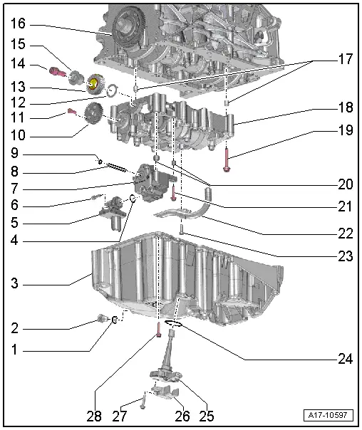
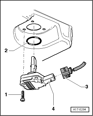
| 1 - | Seal |
| q | Replace |
| 2 - | Oil drain plug |
| q | 30 Nm. |
| 3 - | Oil pan |
| q | Removing and installing → Chapter. |
| 4 - | Bolt. |
| q | 9 Nm. |
| 5 - | Suction pipe |
| q | Clean strainer if dirty |
| 6 - | O ring |
| q | Replace |
| 7 - | Oil pump: |
| q | Removing and installing → Chapter. |
| q | Make sure both dowel sleeves are in place for centring the oil pump in the balance shaft assembly before installing the oil pump. |
| 8 - | Oil pump drive shaft |
| 9 - | Circlip |
| q | Must lie in base of groove. |
| q | Renew damaged or over-tensioned circlip. |
| 10 - | Cylindrical pinion for a balance shaft |
| 11 - | Bolt. |
| q | Replace |
| q | 20 Nm + turn +90° further |
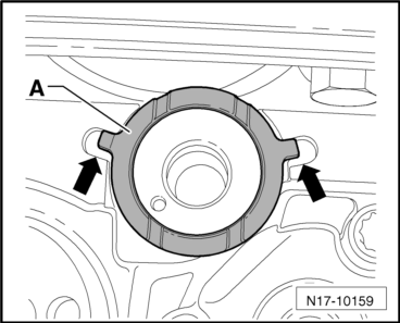
| 12 - | Thrust washer |
| q | For the idler gear |
| q | Replace |
| q | Note installation position → Fig. |
| q | To install intermediate gear wheel, secure to balancer shaft module with grease. |
| 13 - | Intermediate gear wheel |
| q | Replace |
| q | To achieve the correct backlash a suitably thick coating is already applied to the new idler gear; the required clearance is achieved as the coating is worn down |
 Caution
|
| q | Fitting position: Part No. must be visible |
| 14 - | Bolt. |
| q | With washer. |
| q | Replace |
| q | 90 Nm + turn +90° further |
| 15 - | Hub |
| q | For the idler gear |
| q | Replace |
| 16 - | Crankshaft cogwheel |
| 17 - | Dowel sleeves |
| 18 - | Balance shaft assembly |
| q | Removing → Chapter |
| q | Installing new balance shaft assembly → Chapter |
| q | Re-installing "old" balance shaft assembly → Chapter |
| q | Make sure both dowel sleeves are in place for centring the balance shaft assembly on the cylinder block before installing the oil pump. |
| q | Balancer shaft module - specified torques and sequence → Fig. |
| 19 - | Bolt. |
| q | Replace |
| q | Tightening sequence → Fig. |
| 20 - | Dowel sleeves |
| 21 - | Bolt. |
| q | 9 Nm. |
| 22 - | Oil extraction pipe |
| 23 - | Bolt. |
| q | 9 Nm. |
| 24 - | Seal |
| q | Replace |
| 25 - | Oil level/oil temperature sender -G266- |
| q | Removing and installing → Fig.. |
| 26 - | Cover |
| q | For oil level and oil temperature sender -G266- |
| 27 - | Bolt. |
| q | Self-locking |
| q | Replace |
| q | 9 Nm. |
| 28 - | Bolt. |
| q | Replace |
| q | Tightening torque and sequence |
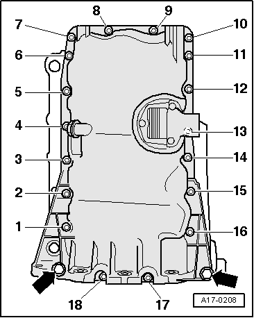
| stage: | Bolts | Tightening torque |
| 1. | -1 … 20- | 5 Nm in diagonal sequence |
| 2. | -Arrows - | 40 Nm. |
| 3. | -1 … 20- | Tighten in stages and in diagonal sequence; final torque 13 Nm. |
|
|
 Note
Note
|
|
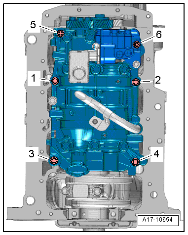
| stage: | Bolts | Tightening torque/angle specification |
| 1. | -1 … 6- | Screw in hand-tight in this sequence |
| 2. | -1 … 6- | Pre-tighten bolts in this sequence to 6 Nm |
| 3. | -1 … 4- | Tighten with 20 Nm |
| 4. | -5 and 6- | Tighten with 13 Nm |
| 5. | -1 … 6- | Use rigid wrench to turn 90° further in this sequence |
Note
|
|