seat Workshop Repair Guides

SEAT Workshop Service and Repair Manuals

Removing and positioning the engine > < Technical data
Engine: removing
Engine: removing
  Note
t  
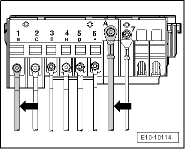
To carry out this work it will be necessary to disconnect battery earth strap. Check whether a coded radio is fitted. Where necessary, check the anti-theft coding first.
t  
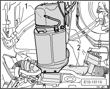
The engine is removed forwards together with the gearbox without mounted particulate filter.
t  So that the steering wheel is not locked, keep the key in the ignition.
t  The front wheels should be removed before proceeding with the removal of the engine assembly. In this way, the vehicle may be lowered using the platform until the protection plates for the disk brakes are almost touching the ground. Thus, the most ergonomic working position is achieved for reaching the components in the engine compartment.
t  All cable ties which are opened or cut through when engine is removed must be replaced in the same position when engine is installed.
t  Some components can not be removed, or only with a great deal of difficulty, while the engine is mounted. All of the faulty or damaged components should be identified before removal and should be replaced before re-installing the engine.
t  
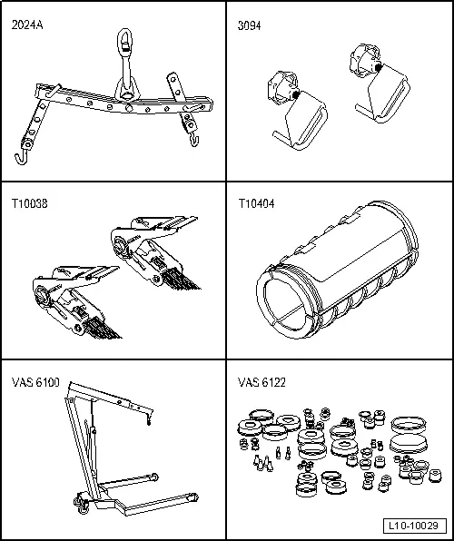
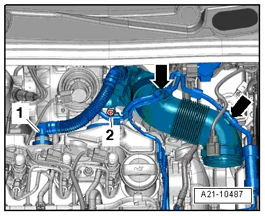
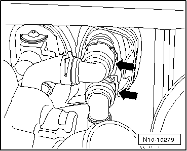
After removing coolant or fuel lines, these must be sealed using the engine sealing plug set -VAS 6122- to prevent dirt from entering or coolant or fuel from running out.
  WARNING
When doing any repair work, especially in the engine compartment, pay attention to the following due to the cramped conditions:
t  Route all the various lines in their original positions.
t  Ensure sufficient clearance for all moving or hot components.
Consult the equivalence table for tools and equipment according to applicability among Seat / VW / Audi / Skoda → Chapter.
   
Special tools and workshop equipment required
t  Lifting tackle -2024A-, see equivalent → Anchor
t  Hose clamps -3094-, see equivalent → Anchor
t  Tension belt -T10038-, see equivalent → Anchor
t  Transport lock -T10404-, see equivalent → Anchor
t  Workshop crane -VAS 6100-, see equivalent → Anchor
t  Engine sealing plug set -VAS 6122-, see equivalent → Anchor
t  Circuit clamp (female) -SAT 1210-, see equivalent → Anchor
t  Circuit clamp (male) -SAT 1211-, see equivalent → Anchor

   
Operation process
–  Before removing the error memory, call-up all control units → Chapter.
–  Remove the engine cover upwards -arrows-.
  WARNING
Hot coolant and vapours can cause burns!
t  When the engine is hot the cooling system is under pressure.
t  To reduce the excess pressure, cover the filler cap of the coolant expansion tank with a cloth and open carefully.
–  Open filler cap on coolant expansion tank.
–  With the ignition switched off, disconnect battery earth strap → Electrical system; Rep. gr.27
–  Dismount the air filter housing together with the air mass meter and the connecting pipe → Chapter.
–  Remove battery → Electrical system; Rep. gr.27
  E10-10085
–  Remove battery carrier, unscrew securing bolts -arrows- for this.
–  Drain coolant → Chapter.
  A10-1572
–  Slacken bolt -2- and remove clamp.
  Note
Disregard -item 1, 3-.
  A26-10721
–  Unscrew the fixing bolts -1- on the top bracket of the particulate filter and undo the fixing bolt of the bracket on the cylinder head by one rotation.
–  Remove the supplementary fuel pump -V393- → Chapter.
–  Remove the fuel filter unit → Chapter
  N26-10374
–  Remove coolant expansion tank and lay down on engine.
–  Remove centre noise insulation -fastening points 1 ... 3-.
  A10-1565
–  Remove left and right noise insulation -securing elements 1 ... 3-.
  Note
The illustration shows the right noise insulation, the removal of the left noise insulation is corresponding.
  A10-1643
–  Unscrew the bolt -arrow- and push the filling neck for the windscreen washer tank to the side.
–  Remove the cowling with the radiator fan -V7- and the radiator fan, right side -V35- → Chapter.
–  Separate the radiator from the intercooler → Chapter.
–  Remove charge air cooler → Chapter.
  N10-10284
–  Disconnect the clamps -2- and -3- from the coolant line on the top side of the right sill.
  Note
Item -1- can be disregarded.
  A19-0486
–  Lash / secure the condenser -1- of the air conditioning system using the tension belt -T10038- as shown in the figure.
–  Remove the lock carrier → Bodywork, exterior fitting work ; Rep. gr.50
–  Remove the Poly V-belt → Chapter.
  E10-10106
–  Disconnect electrical connection -1- for magnetic coupling on air conditioner compressor.
–  Unscrew the bolts -arrows- for air conditioning compressor.
  A10-1637
–  Fit the protective elements at those positions -arrows- so that damage is prevented to the bodywork and the coolant lines.
–  Connect the guide rods -T10093- as shown in the diagram.
–  With the aid of a second colleague and two lashing belts -T10038-, fix the compressor and condenser of the air conditioning system as shown in the diagram.
  E10-10108
–  Remove hose -1- for crankcase ventilation from the cover of the roller rocker fingers. Press-in the tab for releasing.
–  Loosen the vacuum hoses -arrows- on the air pipe.
–  Unscrew bolt -2-. Swivel the intake manifold with intake sleeve to the back and detach it from the exhaust gas turbocharger.
  A21-10487
–  Pull off vacuum hoses -1- and -2- for charge air control.
  N10-10286
–  Detach the connector of the exhaust gas temperature sender 4 -G648--2-.
  Note
Ignore items -1- and -3-.
  N26-10333
–  Disconnect the electrics of the exhaust gas temperature sender from the holders -2- on the bulkhead of the plenum chamber and the retaining clips of the exhaust gas turbocharger.
  Note
t  Item -1- can be disregarded.
t  The electric wiring of the sender must be released in order not to damage them and to enlarge the working space in the particulate filter.
–  Place the electric wires of the exhaust gas temperature sender 4 -G648- on the engine.
  N26-10334
–  Disconnect the vacuum hose -arrow- of the servo brake.
–  Place drip tray for workshop crane -VAS 6208- under point of separation.
  A10-10031
–  Disconnect quick-release couplings for heat exchanger -arrows- on plenum chamber bulkhead.
–  Mount the plugs from the engine sealing plug set -VAS 6122- to the lines and quick connectors of the heat exchanger.
  N10-10279
–  Slide the two clips in the direction of the -arrows- and remove cover from electronics box in engine compartment.
  A10-10349
–  Detach the positive line -arrow- of the starter from the central electrics and place aside on the engine.
–  Unscrew and expose the terminal 30 wire -arrow- in the electronics box (engine compartment).
Vehicles with dual clutch gearbox
–  Remove shift mechanism from gearbox → 6-speed dual clutch gearbox; Rep. gr.30.
  E10-10114
–  To release, turn catch of mechatronic connector -arrow- and pull connector off.
Vehicles with manual gearbox
–  Separate the gear mechanism from the gearbox → Manual gearbox, Actuation, Unit, Differential lock; Rep. gr.34.
  Note
  N10-10278
t  When performing the following operations, care must be taken not to spill brake fluid onto the starter or the gearbox. If fluid comes into contact with them, the affected area must be thoroughly cleaned.
t  Item -B- can be disregarded.
–  Pull out clip -arrow- up until the stop.
–  Remove the plastic line or the pipe and hose assembly -A- from the clutch bleeder / clutch slave cylinder.
–  Connect the opened lines and connections with the lock (bushing) for clutch circuit -SAT 1210- and the lock (connector) for clutch circuit -SAT 1211-.
All vehicles (continued):
–  Remove the windscreen wiper arms and the windscreen trim of the plenum chamber cover → Electrical system; Rep. gr.92.
–  Remove the front plate of the plenum chamber → Bodywork, exterior fitting work; Rep. gr.55
–  Remove engine control unit from its bracket:
t  Engine control unit with antitheft protection: Removing and installing → Chapter.
t  Engine control unit with antitheft protection: removing and fitting → Chapter
  A34-10522
–  Release connector for engine wiring harness -arrow- and pull off from engine control unit.
  N10-10290
–  Release the engine wiring harness guide -arrow- and pull out upwards.
  A10-1574
–  Open cable guide retainer -arrows-.
  Note
Item -1- can be disregarded.
  A10-10563
–  Disconnect connectors -1- and -2- on left longitudinal member.
–  Open the locking mechanism of the cable routing under the plug connector -1-.
  N10-10288
–  Disengage the snap-lock -arrow- and remove and disconnect the plug connector -1-.
  Note
  A10-11185
Use removal lever -80 - 200- to lever out the wiring clips when performing the next work steps.
–  Unclip the engine wiring harness to the control unit from the wiring guide.
–  Remove the engine cable harness from the cable guide on the side member and place it on the engine.
–  Unscrew earth wire on gearbox.
–  Disconnect all connectors between starter, gearbox and body.
  Note
If necessary, fix the lines with cable ties so that they are not in the way when removing and installing the engine.
  A70-0836
–  Disconnect the connector -1- of the oil level and temperature sender -G266-.
  A10-10025
–  Unscrew bolts -1…3- and remove pendulum support.
–  Fit the drive shafts → Running gear, shafts, steering; Rep. gr.40.
  A10-1578
–  Mount the support tool -T10404- onto the vibration damper of the front section of the exhaust pipe with particle filter.
  Note
The mounting on the front section of the exhaust pipe with particle filter should not be bent by more than 10° otherwise there is a risk of damage.
  E10-10105
–  Unscrew the nuts -1- above the bottom bracket of the particulate filter using the Ratchet spanner -T10384-.
–  Remove the nuts -2- and remove the den bracket of the particulate filter.
  A26-10723
–  Unscrew securing nuts from the clamp -1-. In that case it is not necessary to unscrew nuts -arrows-.
  A26-0734
–  Screw out the suspension component -arrows- from the exhaust pipe.
–  Push the particle filter to the left and fix to the front side of the plenum chamber using a suitable system.
  Note
t  Make sure that all lines of the exhaust temperature sender are not exposed to tension and that hey are not damaged when removing the »engine assembly«.
t  Check that all hose and line connections between engine, gearbox and body have been detached.
  A26-0735
–  Hook the suspension device -2024A- as described in the following and, using the »workshop crane«, lift the engine assembly -VAS 6100- into its assembly position.
Vibration damper end: Forth borehole of the perforated flange in position 1.
Flywheel end: Second borehole of the perforated flange in position 7.
  E10-10107
–  Unscrew securing bolts -arrows- of assembly mounting on engine.
  N10-0437
–  Unscrew securing bolts -arrows- of assembly mounting on gearbox.
  Note
Carefully guide »engine/gearbox assembly« when removing to avoid damage to body.
–  Lower »engine/gearbox assembly« slightly and remove forwards.
  N10-0445
–  Place the particle filter-1- on the steering box -2- in order not to damage it as long as the »engine assembly« is not installed.
Secure engine to engine and gearbox support -VAS 6095- to carry out repairs → Chapter.
  E10-10110

Removing and positioning the engine > < Technical data