seat Workshop Repair Guides

SEAT Workshop Service and Repair Manuals

Removing and installing engine > < Engine: Removing and installing
Engine: fitting
Engine: fitting
Consult the equivalence table for tools and equipment according to applicability among Seat / VW / Audi / Skoda → Chapter.
   
Special tools and workshop equipment required
t  counterhold -2024A-, see equivalent → Anchor
t  Hose clamp -3094-, see equivalent → Anchor
t  counterhold -T10038-, see equivalent → Anchor
t  counterhold -T10404-, see equivalent → Anchor
t  Workshop crane -VAS 6100-, see equivalent → Anchor
t  Engine sealing plug set -VAS 6122-, see equivalent → Anchor

Assembly notes:
  Note
t  When fitting, replace the self-locking nuts and bolts.
t  Renew bolts which have a specified tightening angle, as well as seals and gaskets.
t  Secure all hose connections with the correct hose clips (same as original equipment) → Parts catalogue.
t  Clean input shaft splines and, for used clutch plates, hub splines; remove corrosion and apply a thin coat of grease → Parts Catalogue to the splines. Then move the clutch plate on the input shaft from side to side, until the hub moves smoothly on the shaft. Excess grease must be removed.
   
–  Check whether dowel sleeves for centring the engine/gearbox assembly are fitted in the cylinder block; install if necessary.
–  Observe that the intermediate plate is fitted on sealing flange and is slid onto the dowel sleeves -arrows-.
Successive mounting
Installation is carried out in reverse order, noting the following:
t  Vehicles with manual gearbox → 6-speed manual gearbox; Rep. gr.30.
t  Vehicles with dual clutch gearbox → 6-speed dual clutch gearbox; Rep. gr.30.
  A13-0682
–  Hook the suspension device -2024A- as described in the following and, using the »workshop crane«, lift the engine assembly -VAS 6100- into its assembly position.
Vibration damper end: Forth borehole of the perforated flange in position 1.
Flywheel end: Second borehole of the perforated flange in position 7.
–  Set the flywheel side lower than the V-belt / vibration damper side. Remove the respective spindle for this purpose.
Fastening, manual gearbox to engine
–  Check if the driving plate of the clutch is centred → 6 speed manual gearbox; Rep. gr.30.
–  Check clutch release bearing for wear. Renew release bearing and slave cylinder if necessary.
  E10-10107
–  Replace the O-ring -1- on the right gearbox shaft and grease the gear teeth -2- with universal grease → Spare parts catalogue.
–  Bolt gearbox onto engine.
  Note
t  Tightening torques apply only to lightly greased, oiled, phosphated or black-finished nuts and bolts.
t  Additional lubricant such as engine or gearbox oil may be used, but do not use graphite lubricant.
t  Use is never to be made of degreased parts.
t  Tolerance for tightening torques: ± 15 %.
  A34-0638
Fitting engine/manual gearbox
  A30-10043
ItemBolt.Nm
1 1)M12x5580
2 1)M12x16580
3M10x10540
4M10x5040
5 2)M12x6580
ADowel sleeves to centre
l  1) Bolt with stud M8.
l  2) Screwed into gearbox from engine side.

Vehicles with direct shift gearbox
–  Clean the teeth of the gearbox primary shaft and the teeth of the double mass inertial steering, eliminate the corrosion and apply over the teeth a fine layer of universal grease → Spares catalogue. Excess grease must be removed.
–  In engines for vehicles with direct shift gearbox (DSG), there should be a gear needle bearing fitted on the crankshaft. Fit it if necessary → Chapter.
–  Bolt gearbox onto engine.
   
Engine / direct shift gearbox mount
  A34-10045
ItemBolt.Nm
1, 3, 10M12x5580
5M12x6580
6, 7, 8M10x5040
9M12x7080
2, 4Install the starter motor → Electrical system; Rep. gr.27
ADowel sleeves to centre

   
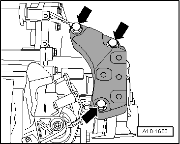
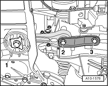
–  Mount the gearbox support and tighten the bolts -arrows- to 60 Nm + 90° (1/4 rotations).
–  When installing the »engine assembly«, take care that sufficient free is at hand to the engine assembly.
Four wheel drive vehicles
–  Mount the angular gear support → Rep. gr.34
–  Mount the right short axle → Rep. gr.40
All vehicles (continued):
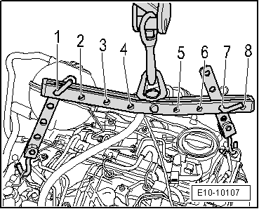
–  Insert the engine/gearbox assembly into the body.
  Note
t  When fitting the engine assembly, continue with care so that the bodywork is not damaged.
t  After working on the particulate filter, ensure it is installed free of stress.
t  Renew self-locking nuts, seals, gaskets and securing clamps.
  Caution
Avoid damage of decoupling element behind particulate filter. When removing and installing:
t  Do not bend decoupling element more than 10°. Secure with transportation lock -T10404-.
t  Install decoupling element so that it is not under tension.
t  Take care not to damage wire mesh on decoupling element.
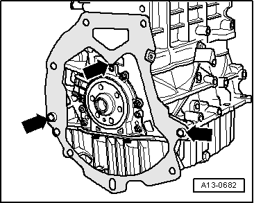
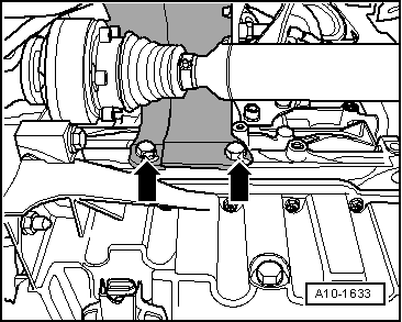
–  Fit the bearing of the engine assembly, engine and gearbox side.
–  Adjusting assembly mountings → Chapter.
  Note
Specified torques for assembly mountings → Chapter
–  Hang-out and remove the workshop crane -VAS 6100- and remove the suspension device -2024A- of the engine.
–  Mount the particle filter → Chapter.
–  Fit the complete half-shafts → Running gear, axles, steering; Rep. gr.40.
  A10-1683
–  Mount the heat protection plate of the right drive shaft -arrows-.
Four wheel drive vehicles
–  Connect the front section of the cardan shaft → Final drive 0AV; Rep. gr.39.
  A10-1633
Continued for all vehicles
–  Secure the pendulum support with the bolts -1 … 3- to the gearbox and subframe. Tightening torque → Chapter
–  Install the exhaust system and align free of stress → Chapter.
–  Install the air conditioner compressor → Heating, ventilation, air conditioning; Rep. gr.87.
–  Install poly V-belt → Chapter.
–  Electrical connections and routing → Current flow diagrams, Electrical fault finding and Fitting locations.
Vehicles with manual gearboxes
–  Remove the lock (bushing) for clutch circuit -SAT 1210- and the lock (connector) for clutch circuit -SAT 1211-.
  A10-1578
–  Insert the tubes and hoses -4- of the clutch mechanism with a new O-ring -3- on the breather connection -1-, until the securing clip clicks audibly into place -2-.
–  To test, pull on the tubes/hoses.
  WARNING
The clutch pedal must not be operated before bleeding the clutch installation of air.
–  Bleed the clutch hydraulic system → Rep. gr.30.
–  Gear selection mechanism: Install and adjust the gearbox → Manual gearbox, Actuation, Unit, Differential lock; Rep. gr.34.
–  Install battery and battery tray → Electrical system; Rep. gr.27.
–  Observe notes after reconnecting battery → Electrical system; Rep. gr.27
Vehicles with direct shift gearbox
–  Mount the control wire of the selector lever and adjust it → Rep. gr.34.
Continued for all vehicles
–  Bring lock plate carrier into service position and leave it there → Bodywork, exterior fitting work; Rep. gr.50
–  Install charge air cooler → Chapter.
–  Fit the supercharger air system hoses and observe the assembly instructions → Chapter.
–  Mount the lock carrier plate completely →  Bodywork, exterior fitting work ; Rep. gr.50
–  Check oil level → Chapter.
–  Fill coolant system with coolant → Chapter.
  Note
t  The drained coolant can only be reused if the cylinder head or the cylinder block have not been replaced.
t  Contaminated or dirty coolant must not be used again.
  WARNING
Do not use a battery charger to start the engine! The control units of the vehicle may be damaged.
–  Filling fuel system → Chapter.
–  Interrogate the fault memory of the control unit → Chapter.
–  Delete all fault entries which may have occurred during installation → Vehicle diagnostic tester„Vehicle self-diagnosis“.
–  Check the headlight settings → Electrical system; Rep. gr.94.
  Note
Observe applicable safety precautions during road test.
–  Perform test drive, and interrogate fault memory afterwards → Chapter.
Tightening torques
  A30-0136
ComponentNm
Bolts/nutsM610
 M715
 M820
 M10:40
 M1265
Except for the following:  
Direct shift gearbox: Starter motor gearbox 40
discrepancies: 
Gearbox support on gearbox.60 + 90° 1)2)
Left supercharger air tube to the oil sump10
Pendulum support to gearbox40 + 90° 1)2)
Pendulum support to sub-frame100 + 90° 1)2)
Lock carrier to the bodywork10
Terminal B+ to starter16
Earth wire to gearbox22
Front supercharger air tube to the engine block22
l  1) Renew bolts
l  2) 90° is equivalent to a quarter turn


Removing and installing engine > < Engine: Removing and installing