seat Workshop Repair Guides

SEAT Workshop Service and Repair Manuals

Enginecrankshaft group, pistons > < Removing and positioning the engine
Adjusting assembly mountings
Special tools and workshop equipment required
   
t  
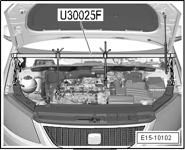
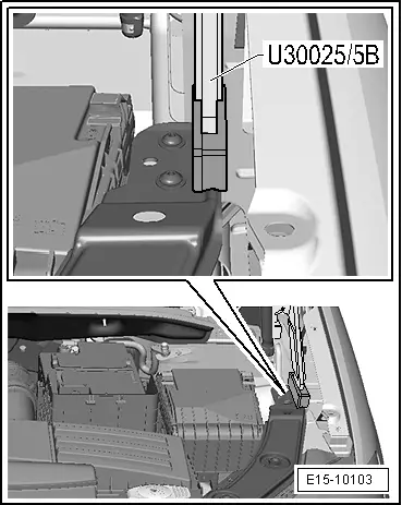
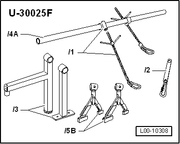
Support bracket -U-30025F-
t  Torque wrench -V.A.G 1331-
t  Spring-type clip pliers -VAS 6362-
Procedure
  WARNING
When doing any repair work, especially in the engine compartment, pay attention to the following due to the cramped conditions:
t  Route lines of any kind so that the original routing can be restored.
t  Ensure that there is sufficient clearance to all moving or hot components.
–  Remove engine cover panel → Chapter.
–  Remove air filter housing → Chapter.
–  Remove intake hose between air mass meter -G70- and intake connecting pipe.
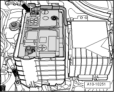
  Caution
To prevent damage to the electronic components when disconnecting the battery:
Observe notes on procedure for disconnecting the battery.
  L00-10308
–  Disconnect the earth connection -arrow- on the battery when the ignition is turned off → Electrical system; Rep. gr.27
  A10-10251
–  Remove battery and battery tray -arrows-.
  A10-1572
–  Set up support bracket -U-30025F- with necessary adapters as illustrated and support engine in installation position.
  Note
  E15-10102
The Adapter -U-30025/5B- of the support bracket must be inserted with the rubber blocks in the direction of the wing. Front application point in the area of the screw of the retaining plate of the front end.
  Note
The securing bolts for the assembly mountings may only be removed if the engine is supported with support bracket -U-30025F-!
  E15-10103
–  Renew engine mounting bolts -arrows- in succession (if not already carried out) and screw in hand-tight.
  N10-0437
–  Renew gearbox mounting bolts -arrows- in succession (if not already carried out) and screw in hand-tight.
–  Loosen bolts for support arms on engine side and on gearbox side by about two turns each.
  N10-0445
Engine support.
l  There must be a distance -a- of at least 10 mm between engine bracket and longitudinal member (right side).
l  The side surface of the engine bracket -2- should be located parallel to the support arm -1-.
  A10-1661
Gearbox mounting
–  Ensure that edges of support arm (on gearbox side) -1- and gearbox mounting -2- are parallel.
l  Dimension -x- must be identical on both sides of mounting.
–  Tighten bolts for assembly mountings:
l  Specified torques → Chapter.
The remaining installation steps are carried out in the reverse sequence. In the process, note the following:
l  Ensure that fuel lines are tight.
l  Do not interchange supply line and return line (return line blue or with blue marking, supply line black).
–  Observe notes after connecting battery → Electrical system; Rep. gr.27.
  A10-1814

Enginecrankshaft group, pistons > < Removing and positioning the engine