seat Workshop Repair Guides

SEAT Workshop Service and Repair Manuals

Valve control > < Engine: Dismantling and assembling
Removal:
Removal:
–  Disconnect earth strap at battery with ignition switched off → Electrical system; Rep. gr.27.
   
–  Remove the engine cover upwards -arrows-.
–  Remove air filter housing → Chapter.
–  Remove the battery and its mount → Electrical system; Rep. gr.27.
–  Remove the cowling with the radiator fan -V7- and the radiator fan, right side -V35- → Chapter.
–  Remove connecting hose on »cold side« → Item from charge air cooler.
–  Remove the cylinder head cover → Chapter.
  E10-10085
–  Pull connector off throttle valve module -J338--2-.
–  Unscrew the oil level control screw -4-.
  Note
Ignore items -1- and -3-.
–  Remove the vacuum line from the vacuum pump.
  N15-10502
–  Unscrew bolts -2, 5- and -arrows-.
–  Free electrical lines and hoses on left air pipe using removal lever -80 - 200-.
–  Release hose clip -3- and remove left air pipe.
  Note
Ignore items -1- and -4-.
  A21-10493
–  Remove bolts -arrows- and detach the impulse absorber -2-.
  Note
Item -1- can be disregarded.
  A21-10478
–  Remove centre noise insulation -fastening points 1 ... 3-.
–  Drain coolant → Chapter.
–  Unplug electrical connector -4- at coolant temperature sender -G62-.
  A10-1565
–  Pull coolant hoses off the connections For this purpose undo hose clamps -1- and -2-.
  A19-10992
–  Disconnect electrical connector -1- on oil pressure switch -F1-.
–  Unscrew bolt -arrow-.
–  Pull off vacuum hose -2-.
  A15-10799
–  Remove electrical connector -3- from bracket and disconnect.
–  Free electrical lines on turbocharger.
  Note
Ignore items -1- and -2-.
–  Remove the air duct with the radiator fan → Chapter.
  A26-10696
–  Unscrew securing bolts -arrows- from charge air pipe and disconnect connector from charge air pressure sender -G31--1-.
–  Open the clamp -2- and lay the coolant hose -3- free and remove the supercharger air hose.
  Caution
Ensure that decoupling element of connecting pipe is not bent and thus stretched. There is a danger of cracking.
  A21-10435
–  Remove connecting pipes for exhaust gas recirculation -A- using socket -T10385-.
  N15-10443
–  Unscrew securing nuts -arrows- of bracket for particulate filter -A- at crankcase.
  N26-10337
–  Unscrew union nut -2- and unscrew bolt -3-.
  Note
Item -1- can be disregarded.
  A21-10446
–  Unscrew bolt -arrow- from rear toothed belt guard.
–  Release connecting clamp between turbocharger and diesel particulate filter.
  N15-10435
–  Unscrew securing bolt from bracket on cylinder head -arrow- and push diesel particulate filter to side.
  N26-10374
–  Unplug the connector of the Hall sender -G40--arrow-.
–  Remove the toothed belt from the camshaft → Chapter.
–  Remove the camshaft sprocket and extract the hub of the camshaft using the extractor tool -T10052-.
–  Unscrew securing nut of toothed belt tensioning roller.
  N15-10416
–  Unplug the connector of the Hall sender -G40--arrow-.
  N15-10416
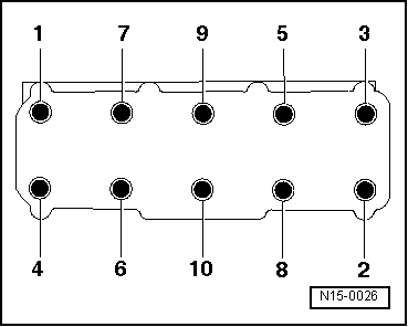
–  Follow the sequence -1 ... 10- for loosening the cylinder head bolts.
  Note
t  A second mechanic is required to remove the cylinder head.
t  The toothed belt tensioning roller is pulled off the stud when the cylinder head is lifted out.
t  The oil return line of the turbocharger is pulled out of the support when the cylinder head is lifted out.
–  Lift the cylinder head on the gearbox side and disconnect from the toothed gear guard. Make sure that toothed belt tensioner does not fall down.
–  Place cylinder head down taking care not to bend oil return line. If necessary, place a piece of wood under exhaust manifold.
  N15-0026

Valve control > < Engine: Dismantling and assembling