
Leon Mk1
| Valve control: Assembly overview |

| 1 - | Valve |
| q | Not to be reworked, only grinding in is permissible |
| q | Mark installation position for re-installation. |
| q | Checking → Chapter |
| q | Valve dimensions → Chapter |
| q | Checking valve guides → Chapter |
| 2 - | Cylinder head |
| 3 - | Valve stem seal |
| q | Replace when cylinder head is installed → Chapter, |
| q | Replace when cylinder head is removed → Chapter |
| 4 - | Valve spring |
| 5 - | Valve plate spring |
| 6 - | Woodruff keys |
| 7 - | Cap |
| q | Renewing |
| q | Removing: Removing sealing cap with retaining frame installed: pierce on one side with an awl and pry out |
| q | Installing: Fit the sealing cap without sealant using a suitable pressure tool. |
| q | Insertion depth 1 … 2 mm |
| 8 - | Oil seal |
| q | Renew → Chapter |
| 9 - | Exhaust camshaft |
| q | Removing and installing → Chapter |
| q | Measuring axial clearance → Chapter. |
| q | Measuring radial clearance → Chapter |
| 10 - | Bolt |
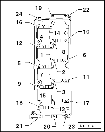
| q | Specified torques and installation sequence → Fig.. |
| 11 - | Ladder-type frame |
| q | With integrated camshaft bearings. |
| q | Specified torques and installation sequence → Fig.. |
| 12 - | Inlet camshaft |
| q | Removing and installing → Chapter |
| q | Measuring axial clearance → Chapter. |
| q | Measuring radial clearance → Chapter |
| 13 - | Roller rocker arms |
| q | Mark installation position for re-installation. |
| q | Check roller bearing for ease of movement. |
| q | Lubricate contact surfaces before installing. |
| 14 - | Securing clip |
| q | For the hydraulic valve compensation element |
| 15 - | Hydraulic compensation element |
| q | Mark installation position for re-installation. |
| q | Lubricate contact surfaces before installing. |
|
|
| stage: | Bolts | Specified torque | ||
| 1. | -1 … 24- | Screw in by hand until they make contact
| ||
| 2. | -1 … 24- | 10 Nm |