seat Workshop Repair Guides

SEAT Workshop Service and Repair Manuals

Silencer > < Pressure differential senderG505: Removing and installing
Particle filter for front wheel drive vehicles: Removing and installing
t  Particle filter for front wheel drive vehicles: Removing → Anchor
t  Particle filter for front wheel drive vehicles: Installing → Anchor.
Consult the equivalence table for tools and equipment according to applicability among Seat / VW / Audi / Skoda → Chapter.
Special tools and workshop equipment required
   
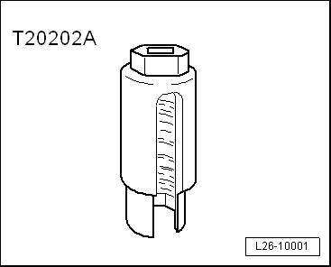
t  Socket wrench 22 mm -T20202A-, see equivalent → Anchor
  L26-10001
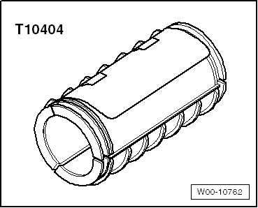
t  Transport lock -T10404-, see equivalent → Anchor
t  Articulated wrench e/c 17 -T20212-, see equivalent → Anchor
t  Torque wrench (5 - 50 Nm) -V.A.G 1331-, see equivalent → Anchor
t  Kit -3253-, see equivalent → Anchor
t  Ratchet spanner -T10384-, see equivalent → Anchor
  W00-10762
Removing .
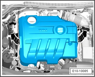
–  Remove the engine cover upwards -arrows-.
  E10-10085
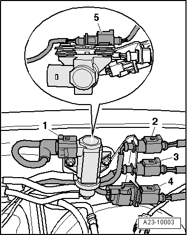
–  Uncouple the electrical connector -5- for the exhaust gas temperature sender 3 -G495- and free the electrical wiring from their fastenings.
–  Uncouple the electrical connector -2- for the exhaust gas temperature sender 4 -G648- and free the electrical wiring.
–  Uncouple the electrical connector -4- from the Lambda probe -G39- and free the electrical wiring from their fastenings.
  A23-10003
–  Unscrew lambda probe -G39--3- with SW 22 socket wrench -T20202A-.
–  Loosen and remove the clip -2- between the particle filter and exhaust gas turbocharger.
  Note
Item -1- can be disregarded.
–  Remove retaining clips of the hose.
–  Carefully and in a straight line, separate the hose from the connecting sleeves (the sleeves of the pressure sender break easily).
  A26-10721
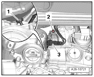
–  Disconnect the connector -2-, undo the bolt -3- and remove the pressure differential sender -G505- with bracket in the direction of the -arrow-.
–  Unscrew the bolt -1- from the upper support of the particle filter mount.
  A26-10722
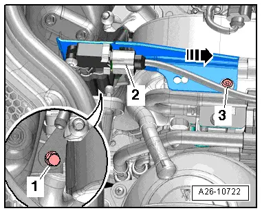
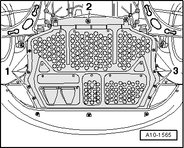
–  Remove centre noise insulation -fastening points 1 ... 3-.
–  Unbolt the front right-hand wheel.
  A10-1565
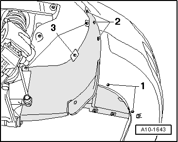
–  Remove right noise insulation -fastening points 1 ... 3-.
  A10-1643
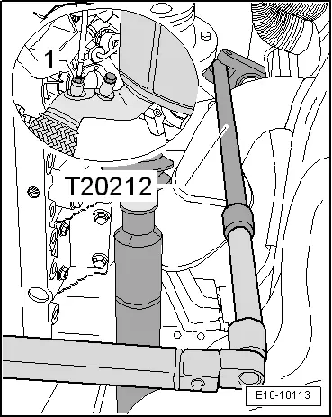
–  Unscrew exhaust temperature sensor 4 -G648--1- with flexible-head wrench SW 17 -T20212-.
  E10-10113
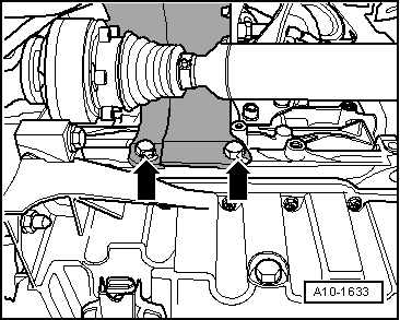
–  Unbolt heat shield for right drive shaft -arrows-.
  A10-1633
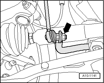
–  Unscrew the nut -arrow- from the connecting rod on the right side of the stabilizer.
  Caution
Risk of damage to the vibration damper section!
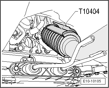
Secure decoupling element with transportation lock -T10404-.
  A10-1141
–  Fit the Die transport lock -T10404-.
  E10-10105
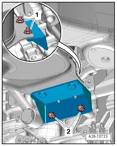
–  Remove nuts -1- and -2-. Nuts -1- can be reached with ratchet wrench 13 mm -T10384-.
–  Removing the bracket of the particle filter.
  A26-10723
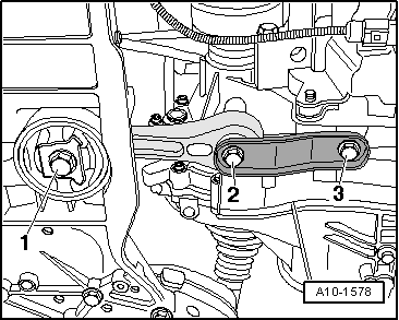
–  Unscrew bolts -2- and -3- of the pendulum arm support.
  Note
Item -1- can be disregarded.
  A10-1578
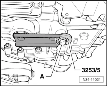
–  Press engine/gearbox assembly to lock carrier and support using pendulum support as shown in illustration.
A - Collared bolt M10x35
  N34-11021
–  Unscrew the right hand drive shaft from the drive flange or the intermediate bearing.
–  Tie the left half-shaft leaving it suspended.
–  Turn the steering toward the right.
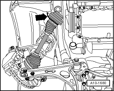
–  Tilt the right-half shaft forwards and strap it to the sill -arrow-, as shown in the image.
–  Remove the thermal protection plate of the steering box assembly.
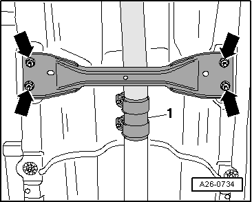
–  Loosen nuts for clamping sleeve -1- and slide clamping sleeve backwards.
  A10-1680
–  Unscrew the nuts -arrows- and remove front cross member from the floor of the vehicle.
  A26-0734
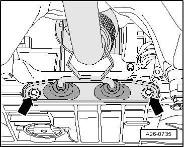
–  Unscrew bolts -arrows- for bracket.
–  Partially remove the front part of the exhaust tube with particulate filter and position it over the steering box.
  A26-0735
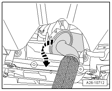
–  Remove particulate filter by turning 180° around its own axis.
Fitting .
l  Tightening torques → Chapter
Installation is carried out in reverse order, noting the following:
  Note
t  When replacing the particle filter, the transport protection on the coupling element should not be removed until just before fitting.
t  Fit the cable clamps in the same position as they were.
t  Ensure that the double clamp for the particle filter is correctly fitted.
t  Replace seals, gaskets and self-locking nuts.
t  The flexible hose sleeves and the line of the turbocharger air system must be free from oil and grease before assembly.
t  Secure all hose connections with the correct hose clips (same as original equipment) → Parts catalogue.
  A26-10712
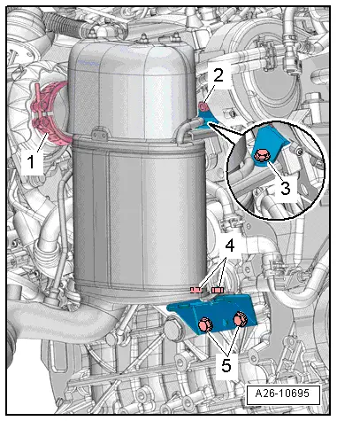
–  Observe sequence when installing particulate filter:
  A26-10695
1.position particulate filter on turbocharger and secure clip -1- loosely
2.screw bolts -2 … 5- in loosely by hand
l  particulate filter and retainer must be able to move
3.tighten clip -1-
4.Tighten the bolts -2- and -5-.
5.Tighten the bolts -3- and -4-.

–  Install pendulum support → Chapter.
–  Fit the drive shafts → Running gear; Rep. gr.40.
   
–  Mount the heat protection plate of the right drive shaft -arrows-.
–  Install exhaust gas temperature sender 3 -G495- → Chapter.
–  Mount the exhaust gas temperature sender 4 -G648- → Chapter.
–  Install the Lambda probe -G39- with Lambda probe heater -Z19- → Chapter
–  Install the pressure differential sender -G505- → Chapter.
–  Align exhaust system free of stress → Chapter.
–  After renewing particulate filter, carry out adaptation in „guided functions“ operating mode → Vehicle diagnostic, testing and information system VAS 5051.
  A10-1633

Silencer > < Pressure differential senderG505: Removing and installing