seat Workshop Repair Guides

SEAT Workshop Service and Repair Manuals

Pressure capsule with charge pressure actuator position senderG581: replace > < Exhaust turbocharger - Assembly overview
Removing and installing turbocharger
t  Exhaust gas turbocharger : Removing → Anchor
t  Exhaust gas turbocharger : Fitting → Anchor
Consult the equivalence table for tools and equipment according to applicability among Seat / VW / Audi / Skoda → Chapter.
Special tools and workshop equipment required
   
t  Socket wrench insert -T40055-, see equivalent → Anchor
  W00-10099
t  
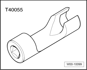
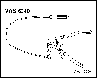
Pliers for spring-loaded band-type clamps -VAS 6340-, see equivalent → Anchor
t  Torque wrench (5 - 50 Nm) -V.A.G 1331-, see equivalent → Anchor
Removing
  Note
When fitting the heat protection plate, fit to the same location.
–  Observe rules for cleanliness → Chapter.
  Caution
If a mechanical fault is discovered on the turbocharger (e.g. a destroyed compressor impeller), it is not sufficient to just renew the turbocharger. To avoid any subsequent damage, the following work must be carried out:
t  Check air filter housing, air filter element and air inlet hoses for contamination.
t  Check the process of the charge air circuit and the charge air cooler for foreign particles.
t  If foreign objects are discovered in the charge air system, clean the charge air path and, if necessary, renew the charge air cooler.
–  Remove particulate filter → Chapter.
–  Remove the air filter housing → Chapter.
  W00-10380
–  Disconnect the crankcase breather hose -1- for the cylinder head cover. To do so, press the tabs.
–  Free vacuum hoses -arrows- at air pipe.
–  Unscrew bolt -2-, swing air pipe with inlet connection to rear and pull from turbocharger.
  A21-10487
–  Remove heat insulation sleeve.
–  Pull vacuum hose -2- from turbocharger vacuum unit.
–  Separate vacuum hose -3-.
–  Disconnect electrical connector -1- at position sender for charge pressure positioner -G581-.
  A21-10338
–  Free electrical connector -3- for exhaust temperature sender 1 -G235- and electrical line.
  Note
Ignore positions -1- and -2-.
  A26-10696
–  Remove bolts -arrows-.
–  Release hose clip -1- and remove pulsation damper -2-.
  A21-10478
–  Remove the connecting pipe -2- for the exhaust gas recirculation.
  S26-0317
–  Unscrew bolts -1, 3-, union nut -2- and screw out together with the socket wrench insert -T40055- and banjo bolts -4, 5-, and remove turbocharger support with oil supply line.
  A21-10502
–  Unscrew bolts -arrows- and remove heat shield.
  A21-10480
–  Remove nuts -arrows-.
–  Remove turbocharger with exhaust manifold from cylinder head, turning so that intake side points down. Remove turbocharger and exhaust manifold downwards.
Installing
l  Tightening torques → Chapter
Installation is carried out in reverse sequence; note the following:
  Note
t  Renew seals, gaskets, O-rings and self-locking nuts.
t  Fill turbocharger with engine oil at connection for oil supply line.
t  Hose connections and air pipes and hoses must be free from oil and grease before fitting.
t  Secure all hose connections with the correct type of hose clips (same as original equipment) → Electronic parts catalogue.
t  After installing turbocharger, run engine for about 1 minute at idling speed to ensure that oil is supplied to turbocharger.
t  Reinstall heat insulation sleeves in the original positions when installing.
l  The sequence of the actions must be maintained so that a tension-free assembly of the combined flange (oil supply and oil return lines) is guaranteed together with the support of the exhaust gas turbocharger.
l  Furthermore this ensures that the turbocharger support is installed tension-free between crankcase and turbocharger.
–  Fit the combined flange (oil supply and oil return lines) to the exhaust gas turbocharger and cylinder block together with the support of the exhaust gas turbocharger.
–  Fit oil supply line onto turbocharger and crankcase.
  A21-10481
–  First bring the bolts -1- and the hollow bolt -4- of the exhaust gas turbocharger to the engine block by hand.
–  Fix the screw -3- to the exhaust turbocharger.
–  Then move the union nut-2- and the banjo bolt -5- for the oil supply line.
–  Then insert the bolt -1- → Item, the banjo bolt -4- in the cylinder block → Item and tighten the support of the exhaust gas turbocharger -3- → Item one after another and in several stages to the specified tightening torque.
–  Finally tighten the bolt on the oil supply line/turbocharger support clamp.
Tightening torques → Chapter
  A21-10502
–  Install the connecting pipe -2- for the exhaust gas recirculation → Chapter.
–  Mount air intake hoses with screw clamps → Fig..
–  Connect vacuum hoses → Chapter.
–  Electrical connections and routing → Current flow diagrams, Electrical fault finding and Fitting locations.
–  Install air cleaner housing → Chapter.
–  Mount the particle filter → Chapter.
–  Check oil level → Chapter.
  S26-0317

Pressure capsule with charge pressure actuator position senderG581: replace > < Exhaust turbocharger - Assembly overview