
Leon Mk1
| Injectors: Assembly overview |

| 1 - | Oil seal |
| q | In rocker finger cover |
| q | Removing and installing → Chapter |
| 2 - | Copper washer |
| q | Renewing |
| 3 - | O ring |
| q | Renewing |
| 4 - | Injector |
| q | The following components and seals or O-rings must be replaced after each installation or removal: „Copper washer“„O-ring of the injector valve adapter shaft“ and „O-ring on the injector valve return connection“. |
| q | The following components and seals/O-rings must always be renewed when an injector is renewed: „clamping piece“, „copper seal“, „O-ring for injector shaft“ and „O-ring for injector return connection“. |
| q | When re-installing the „high-pressure injector pipe“, a visual check of the taper seats must be made for damage (such as scores or corrosion). Always renew if such damage is determined. |
| q | If they are to be reinstalled, the injectors, high-pressure lines and clamping pieces must only ever be refitted on the same cylinder. |
| q | Removing and installing → Chapter |
| 5 - | O ring |
| q | Renewing |
| 6 - | Fuel return line |
| q | To the fuel tank |
| q | Must not be kinked, damaged or clogged. |
| q | Do not dismantle |
| q | After exchanging, engine must be run at idling speed for approx. 2 minutes to bleed fuel system. Then check fuel return lines for leaks. |
| 7 - | 8 Nm + turn 180° further |
| q | Renewing |
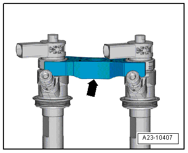
| 8 - | Clamping piece |
| q | If they are to be reinstalled, the injectors and clamping pieces must only ever be refitted on the same cylinder. |
| q | When an injector is renewed, the clamping piece must be renewed at the same time. |
| q | Installation position → Fig. |
| 9 - | High-pressure line, 28 Nm |
| q | Between fuel rail and injectors. |
 Note
Note| t | Observe cylinder specific markings when reusing high-pressure lines. |
| t | The high-pressure pipes can be re-used after performing the following checks: |
| t | Check sealing cone on corresponding high pressure line for deformation and cracks. |
| t | The inside of the line must not show any signs of deformation, changes or damage. |
| t | Rusty lines must not be used again. |
| q | Do not fit under stress |
| 10 - | 22 Nm |
| 11 - | Fuel rail |
| q | Removing and installing → Chapter |
| 12 - | Fuel return hose |
| 13 - | Fuel pressure regulating valve -N276-, 80 Nm. |
| q | Always renew after removing |
| q | Removing and installing → Chapter |
| 14 - | O ring |
| q | Renewing |
| 15 - | High-pressure line, 28 Nm |
| q | Between high-pressure pump and fuel rail |
Note| t | Observe cylinder specific markings when reusing high-pressure lines. |
| t | The high-pressure pipes can be re-used after performing the following checks: |
| t | Check sealing cone on corresponding high pressure line for deformation and cracks. |
| t | The inside of the line must not show any signs of deformation, changes or damage. |
| t | Rusty lines must not be used again. |
| 16 - | 8 Nm |
| q |
| 17 - | Fuel pressure sender -G247-, 100 Nm |
| q | Always renew after removing |
| q | Removing and installing → Chapter |
| 18 - | Grommet |
| q | In rocker finger cover |
|
|