seat Workshop Repair Guides

SEAT Workshop Service and Repair Manuals

Engine cylinder head, valve gear > < Engine: Disassembling and assembling
A - Mount the seal along with the sender wheel on the assembly toolT10134
A - Mount the seal along with the sender wheel on the assembly tool -T10134-
   
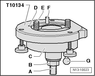
–  Tighten the hexagonal nut -B- to just before the threaded spindle attachment surface -A-.
  N13-10023
–  Secure the centre guide -T10134- on the attachment surface -A- of the threaded spindle in a vice.
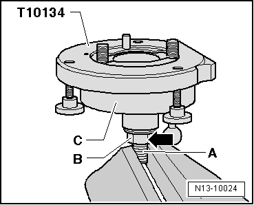
–  Press down on the installation socket -C- so that it rests on the hexagonal bolt -B--arrow-.
–  Screw the hexagonal onto the threaded spindle until the interior of the assembly device and the assembly socket are at the same level.
  N13-10024
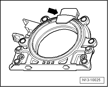
–  Unscrew the attachment clip -arrow- from the new sealing flange.
  Note
Do not remove the sender crown from the sealing flange or change its position.
  N13-10025
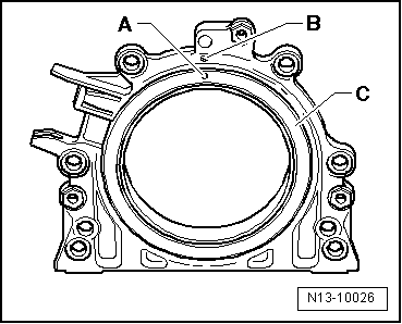
–  The locking hole -A- on the sender wheel -C- must coincide with the mark -B- on the sealing flange.
–  Secure the sealing flange by the front on a flat, clean surface.
  N13-10026
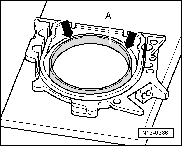
–  Press the sealing lip pressure ring -A- in the direction of the arrow downwards until it rests on the flat surface.
  N13-0386
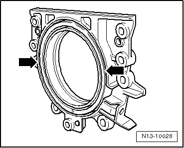
–  The upper edge of the sender wheel and the front edge of the sealing flange must coincide -arrows-.
  N13-10028
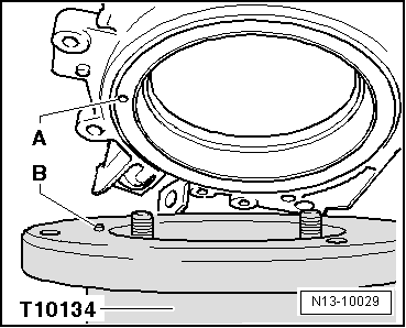
–  Place the sealing flange with the front side on the Fitting device -T10134- in such a way that the locating pin -B- fits into the hole -A- of the sender wheel.
  Note
Ensure that the sealing flange is flat on the installation device.
  N13-10029
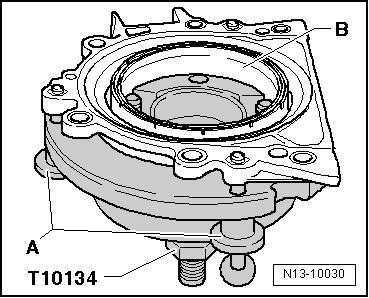
–  When tightening the knurled bolts -A- on the fitting device -T10134-, press the sealing flange and the sealing lip pressure ring -B- so that the position pin does not come out of the hole in the sender wheel.
  Note
Ensure that the sender wheel remains secured in the fitting device when fitting the sealing flange.
  N13-10030

Engine cylinder head, valve gear > < Engine: Disassembling and assembling