seat Workshop Repair Guides

SEAT Workshop Service and Repair Manuals

Engine: dismounting > < Technical data
Engine: dismounting
Engine: dismounting
  Note
t  To carry out this work it will be necessary to disconnect battery earth strap. Therefore check whether a coded radio is fitted. Where necessary, check the anti-theft coding first.
t  The engine is removed from underneath together with the gearbox.
t  
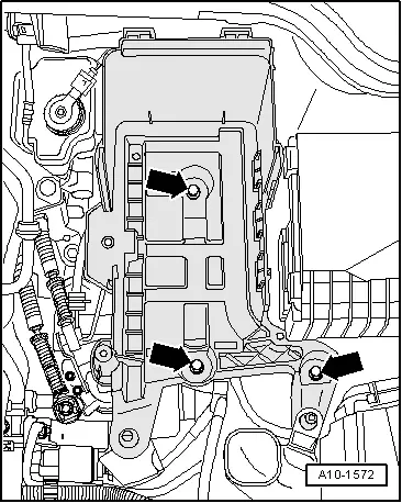
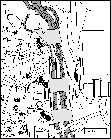
All the cable fixings that are opened or cut during removal of the cylinder head must be fitted in the same position when reinstalling the engine.
  Caution
When doing any repair work, especially in the engine compartment, pay attention to the following due to the cramped conditions:
t  
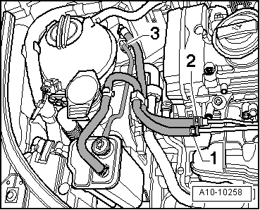
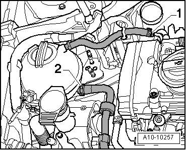
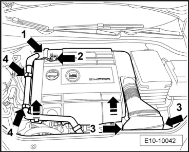
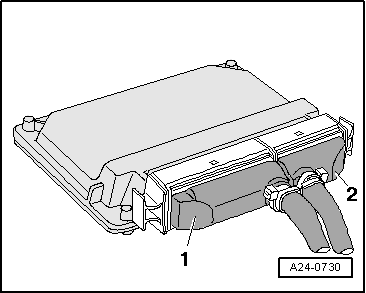
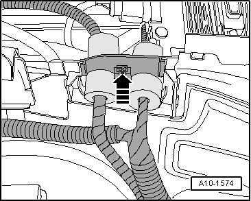
Route all the various lines (e.g. for fuel, hydraulics, active carbon filter system, coolant, refrigerant, brake fluid and vacuum pipes and hoses) and electrical wiring so that the original positions are restored.
t  In order to prevent damage to the pipes all moving or hot parts must be easily accessible.
–  With the ignition switched off, disconnect the battery earth lead → Electrical system; Rep. Gr.27.
   
Vehicles with engine code BWA
–  Remove the suction hose -1-.
–  Pull out the plug -2-.
–  Remove the bolts -3-.
–  Remove the engine cover, by pulling firmly upwards.
  E10-10033
Vehicles with engine code BWJ
–  Remove the suction hose -1-.
–  Disconnect hose from the attachment clamps -4-.
–  Pull out the plug -2-.
–  Remove the bolts -3-.
–  Remove the engine cover, by pulling firmly upwards.
Continued for all vehicles
–  Remove battery → Electrical system; Rep. Gr.27.
  E10-10042
–  Remove battery tray -arrows-.
–  Remove the front panel of the plenum chamber → Bodywork, exterior fitting work; Rep. Gr.50.
–  Remove engine control unit → Chapter.
  A10-1572
–  Disconnect connection -1- from the engine wiring harness.
  A24-0730
–  Release the engine cable harness guide -arrow-, and pull out upwards.
  A10-1574
–  Open the locks of the side member cable guide -arrows-.
–  Disconnect all the connectors of the engine/bodywork cable harness, and leave cable harness on top of the engine.
  A10-1575
–  Move both bolts in the direction indicated by the -arrow- and remove the electrical module cover (engine compartment).
  A10-10349
–  Unscrew and expose the terminal 30 wire -arrow- in the electronics box (engine compartment).
–  Remove both front wheels.
–  Remove the central soundproofing pan → Bodywork, exterior fitting work; Rep. Gr.50.
–  Remove the primary exhaust pipe with catalytic converter → Chapter.
  A10-1883
–  Remove the lower elements on the left and right of the wheel arches, fastening points -1 to 3-.
  A10-1566
–  Remove the supercharger air hoses -arrows-.
  N10-10090
Vehicles with 02Q 4WD gear change
–  Unbolt heat shield for right drive shaft -arrows-.
  A10-10260
–  Check to see if a -colored- is marked on the flexible disk and on the flange on the front tapered unit-arrows-.
If there are no marks, the position of the flexible disc with regard to the flange on the front tapered unit shoul be marked -arrows-.
  Caution
Mark the position of the bolts, as some of these may have balance washers to prevent vibration.
  Note
t  Remember not to unscrew the bolts completely.-1-
  N39-0836
t  Unscrew the bolts one or two turns -1- from the central elastic mount for the cardan shaft.
  E26-10036
–  Release the flector on the cardan shaft on the bevel gear -arrows-, supporting it with a lever held against the triangular flange.
  Note
  A10-10247
t  Do not allow the cardan shaft to fall to one side when removing; Keep it horizontal when separating from the centring pivot. Do not damage the O-ring on the centring bush-arrow-.
t  The flexible disk and vibration damper cannot be separated.
Place the cardan shaft on the steering box.
  V39-1817
Vehicles with front wheel drive:
–  Unbolt heat shield for right drive shaft -arrows-.
Continued for all vehicles
–  Unbolt the driveshaft from the gearbox flange, to the left and right → Running gear, shafts, steering; Rep. Gr.40.
–  Fasten the left-hand drive shaft in a high position.
  WARNING
To loosen the combi bolt for drive shaft, the wheel bearing must not be loaded (the vehicle must not stand on the wheels).
  A10-1633
–  Undo the combi bolt -2- on the right-hand drive shaft. To prevent rotation pump the brake (a second mechanic is necessary).
–  Detach the link rod from the stabiliser bar.
  Note
To prevent changes to the alignment, do not remove the ball joint or the suspension axle-journal.
–  Release the right-hand side driveshaft from the gearbox flange, and move it towards the rear of the vehicle.
–  Dismount the right-hand drive shaft using the extractor -T20001A-. In order to separate the drive shaft it may be necessary to move the engine assembly in the opposite direction to the direction of travel.
–  Drain coolant → Chapter
  WARNING
Fuel supply pipes are pressurised. Use protective goggles and clothing to prevent injuries and contact with the skin. Before releasing the connections on the hoses, place absorbent cloths round the connection. Then dissipate pressure by carefully pulling off hose.
  A40-0444
–  Mark the fuel pipe -2- and the pipe to the activated carbon tank -1-.
–  Disconnect the fuel pipe -2- and set aside.
–  Disconnect the pipe on the activated carbon tank -1- and set aside.
–  Remove the depressurising pipe -3- leading to the activated carbon tank by pressing on the tabs to unlock.
–  Pull the activated carbon tank up and out.
  A10-10258
–  Disconnect the coolant hoses -1 and 2-.
–  Bring lock carrier into service position, with mechanical components → Bodywork, exterior fitting work; Rep. Gr.50.
  A10-10257
Vehicles with air conditioning:
–  Release the coolant hose bracket on the right-hand longitudinal member -arrow-.
–  Drain the air conditioning → Rep. Gr.87
  A10-1740
–  Unbolt the air-conditioner pipe -arrow- on the compressor.
  A10-10262
–  Disconnect the air duct -arrow- of the intercooler.
  A21-10050
–  Unbolt the air-conditioner duct on the condenser -arrow-.
  A10-10308
Continued for all vehicles
–  Unscrew the bolts crossways -1 ... 3- and remove the pendulum support.
  A10-1578
–  Screw in the screws -arrow- of the assembly mounting (on the motor side) by approx. 2 rotations loose into the camshaft.
  A10-1642
–  Screw in the screws -arrow- of the assembly mounting (on the gearbox side) by approx. 2 rotations loose into the camshaft.
–  Disconnect all other electrical connections as necessary from engine/gearbox, and lay to one side.
–  Disconnect all other coolant, vacuum and intake hoses from the engine.
  N10-0445
–  Release the bolts from above -1-.
  A19-10146
–  Remove the air duct -1 and 2- to the inter-cooler.
  A21-10051
–  Pull out the plug -2-.
–  Unscrew bolts -3- and take fan cowl out downwards.
  A19-10146
–  Unscrew connector -1- from the left side member and leave the cable uncovered.
–  Disconnect the air duct -arrow- of the intercooler.
  A19-10149
Vehicles with 02Q manual gear change, 4WD
–  Unclip securing clips -1- and -2- on both control cables.
–  Remove the securing elements for the control cables from the selection and relay rods.
  A34-0620
–  Remove the control cable bracket -arrows- from the gear box and set the cables aside, taking care not to damage them.
Vehicles with 02Q manual gear change, front wheel drive
–  The switching activity by reducing manual → gearbox 02Q front-wheel; Rep. Gr.34.
  Caution
Do not depress clutch pedal after removing slave cylinder hose.
  A34-0621
–  Prevent air escaping from the joint between the rigid pipe - hose -A- leading to the cylinder by choking the hose with the hose clip -3094-.
–  Remove the the rigid flexible hose clip -arrow- up to the stop.
–  Remove the rigid/flexible tubes from the drain valve/clutch cylinder.
Vehicles with 02E automated manual gearbox
–  Remove the wire from the gear selector → lever transmission selector 02E; Rep. Gr.34.
  N34-10002
Continued for all vehicles
–  Release the coolant pump -V50--arrows-.
  A10-10309
–  Move the support -T20205- close to the hydraulic jack -SAT 1040- and turn the bolt -4- until it is parallel with the engine block.
–  From the rear of the engine -A-, first insert the fixed column -1-, then adjust the mobile column -2- as necessary and then screw on the nuts -arrows-.
–  From the front of the engine -B-, position the mobile column -6- and adjust the bolt -5-.
–  Adjust the bolt -3- to immobilise the support -T20205-.
–  Raise the engine and gearbox slightly using the hydraulic jack -SAT 1040-.
  Note
To loosen the mounting bolts, use the stepladder -VAS 5085-.
  E10-10043
–  Unbolt assembly mounting support from above, engine side, from the engine bracket -arrows-.
  N10-0437
–  Unbolt assembly mounting support from above, gearbox side, from the gearbox bracket -arrows-.
  Note
Engine and gearbox must be guided carefully when lowering to prevent damage to the bodywork.
–  Carefully lower the engine and gearbox.
  N10-0445

Engine: dismounting > < Technical data