seat Workshop Repair Guides

SEAT Workshop Service and Repair Manuals

Component testing > < Exhaust turbocharger
Motronic engine control unitJ220 with locking device: removing and fitting
Motronic engine control unit -J220- with locking device: removing and fitting
Removing → Anchor.
Installing → Anchor.
Consult the equivalence table for tools and equipment according to applicability among Seat / VW / Audi / Skoda → Chapter.
Special tools and workshop equipment required
   
t  Electric knife -V.A.G 1561 A-, see equivalent → Anchor
  W00-0532
t  
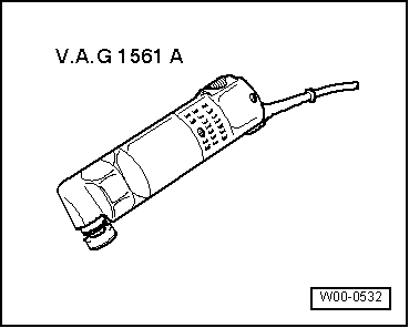
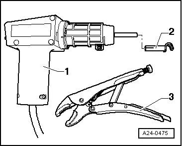
Hot-air gun -1- from the cable repair kit -VAS 1978A-
t  
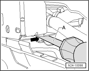
Connectable nozzle -2- (also from the cable repair kit -VAS 1978A-)
t  Self-locking pliers, sold commercially (gripping jaws) -3-
  Note
To replace the engine control unit, connect the central diagnosis -VAS 5051B- or central diagnosis -VAS 5052- and complete the guided function “Replace control unit”.
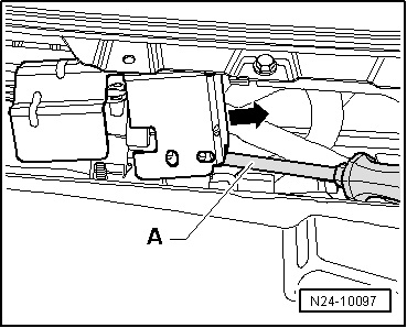
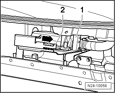
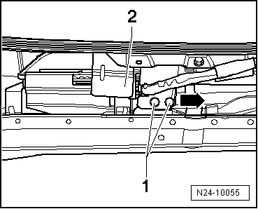
removing
–  Switch off ignition and remove key.
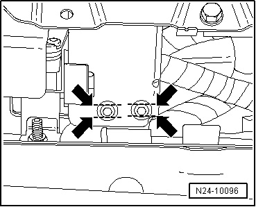
–  Remove the front panel of the plenum chamber → Bodywork, exterior fitting work; Rep. Gr.50.
  Note
The thread on the breakaway bolts has been treated with a threadlocker. The effect of the threadlocker is reduced by heating the breakaway bolts with a hot air gun.
  WARNING
It is essential to prevent damaging (burning) cables and connectors, insulation and control units, therefore, the procedure below must be followed exactly. Remember the instructions for using the hot-air gun.
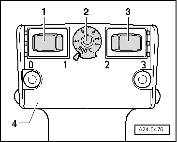
Carry out the adjustments on the hot air blower -4- as described below:
  A24-0475
–  Turn the temperature control button -2- to the maximum heating power (600 °C).
–  Set the two-level switch for air flow -3- to position 3.
  WARNING
When breakaway bolts are heated, some parts of the protective casing become very hot. Do not burn yourself! Also, make sure that, as far as possible, you only heat the breakaway bolt and not adjoining parts. If necessary, cover these parts.
–  Connect the hot-air gun and heat the breakaway bolts.
–  Release the breakaway bolts with the self-locking pliers.
  Note
  A24-0476
If the bolts cannot be loosened, the heads of the split bolts must be sawn to create two flat parallel surfaces -arrows-, after which they can be loosened.
–  Release the breakaway bolts with the self-locking pliers.
  N24-10096
–  Insert a screwdriver -A- between the protective cover and the retention plate -arrow-.
  N24-10098
–  Lift the protective cover by levering it with a screwdriver -A-, and remove it from the retention plate sideways -arrow-.
  N24-10097
–  Unlock front connector -1- from engine control unit and pull it off.
–  Lift the lock slightly -2-, by levering it.
–  Then remove the engine control unit from the support -arrow-.
–  Unlock rear connector from engine control unit and pull it off.
Fitting
–  Remove the remains of the threadlocker from the breakaway bolt holes. A male thread tap can be used for this.
–  Connect the rear connector to the engine control unit and lock.
–  Fit the engine control unit onto the retention plate.
–  Now connect the front connector to the engine control unit and lock.
–  Mount the protective cover on the retention plate.
–  Use new breakaway bolts.
  N24-10056
–  Tighten the breakaway bolts -1- evenly until they break.
–  Remove the front panel of the plenum chamber → Bodywork, exterior fitting work; Rep. Gr.50.
  N24-10055

Component testing > < Exhaust turbocharger