seat Workshop Repair Guides

SEAT Workshop Service and Repair Manuals

Engine lubrication > < Toothed belt drive
Replacing valve shaft seals.
t  Removing → Anchor
t  Installing → Anchor
(With cylinder head installed)
   
Consult the equivalence table for tools and equipment according to applicability among Seat / VW / Audi / Skoda → Chapter.
Special tools and workshop equipment required
t  Spanner -3122B-, see equivalent → Anchor
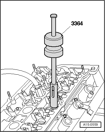
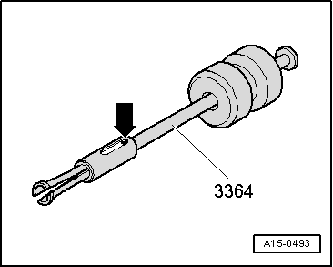
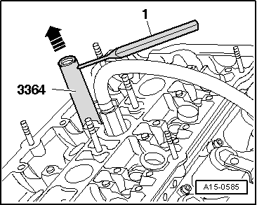
t  Extractor -3364-, see equivalent → Anchor
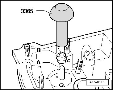
t  Pressure tool -3365-, see equivalent → Anchor
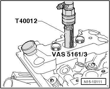
t  Measuring tool -T40012-, see equivalent → Anchor
t  Torque wrench -VAG 1331-, see equivalent → Anchor.
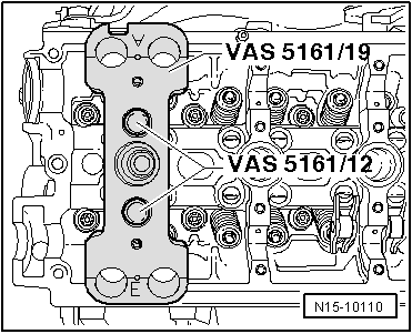
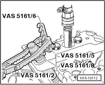
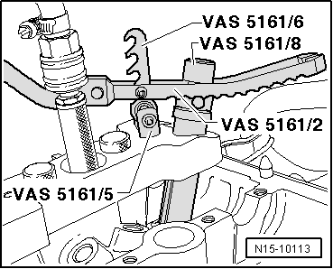
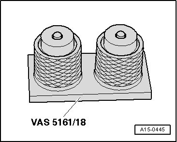
t  Valve insertion socket -VAS 5161-, please see Correspondence → Anchor
t  Template -VAS 5161/19B-, see equivalent → Anchor

Removing
–  Remove camshafts → Chapter.
–  Remove roller rocker arms and place on a clean surface. Ensure that roller rocker arms are not mixed up.
–  Unscrew the spark plugs using spark plug spanner -3122 B-.
   
–  Fasten the template -VAS 5161/19- with the knurled bolts -VAS 5161/12- to the cylinder head, as shown in the figure.
–  Set piston of appropriate cylinder to „bottom dead centre“.
–  Screw the measuring tool -T40012- into the thread and apply compressed air (min. 6 bar).
  N15-10110
–  If the valve cones are tightly seated, they must be loosened using the awl -VAS 5161/3- and a plastic hammer.
  N15-10111
–  Screw the locking element -VAS 5161/6- with the coupling prong -VAS 5161/5- into the template -VAS 5161/19-.
–  Insert the assembly cartridge -VAS 5161/8- in the guide plate -VAS 5161/19-.
–  Attach the pressure prong -VAS 5161/2- to the locking element -VAS 5161/6-.
  Note
  N15-10112
On the exhaust side, attach the pressure prong -VAS 5161/2-, as shown in the figure.
–  Push down the assembly cartridge -VAS 5161/8-. Turn the knurled bolt of the assembly cartridge -VAS 5161/8- towards the right at the same time, until the ends fit into the valve cones.
–  Move the assembly bolt slightly from side to side to loosen the cones from the valves, and catch them in the assembly cartridge.
–  Release the pressure prong -VAS 5161/2-.
–  Remove the assembly cartridge -VAS 5161/8-.
  N15-10113
–  Remove the valve stem seals using the extractor -3364-.
  A15-0559
–  If the extractor -3364- cannot be used on account of restricted space, knock out pin -arrow- with a punch and remove the impact extractor attachment.
  A15-0493
–  Place the bottom side of the extractor -3364- on the valve stem seal.
–  Insert an awl -1- into the hole, at the bottom of the extractor.
–  Attach an iron bar to the assembly tool, and extract the valve stem seal -arrow-.
Fitting
  A15-0585
–  To prevent damage to the new valve stem seals -B-, attach plastic sleeve -A- to valve stem.
–  Lubricate the lip of valve stem seal -B- with oil, position it on the pressure tool -3365- and carefully slide the seal onto the valve guide.
–  Remove the plastic sleeve -A-.
–  Insert valve spring and valve spring plate.
–  Mount the valve assembly set -VAS 5161- as shown in the figure.
  A15-0282
Inlet side
  N15-10112
Exhaust side
  Note
  N15-10113
t  If the valve cones were extracted from the assembly cartridge, they must be placed on the base -VAS 5161/18-.
t  Push the assembly cartridge -VAS 5161/8- down onto the base, and fit the valve cones.
–  Push the assembly cartridge -VAS 5161/8- down with the pressure prong -VAS 5161/2-, and turn the knurled bolt of the assembly cartridge in and out continuously, pulling up at the same time.
–  Release the pressure prong -VAS 5161/2- with the knurled bolt fastened.
–  Detach the value assembly -VAS 5161-.
Continue installation following reverse order for removing.
–  Install camshafts → Chapter.
  A15-0445

Engine lubrication > < Toothed belt drive