seat Workshop Repair Guides

SEAT Workshop Service and Repair Manuals

Removing and installing the balance shaft, exhaust side > < Removing and installing the chain of the balance shaft
Removing and installing the balance shaft, intake side
Removing → Anchor.
Installing → Anchor.
Consult the equivalence table for tools and equipment according to applicability among Seat / VW / Audi / Skoda → Chapter.
Special tools and workshop equipment required
   
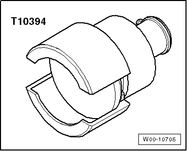
t  Extractor -T10394-, see equivalent → Anchor
  W00-10705
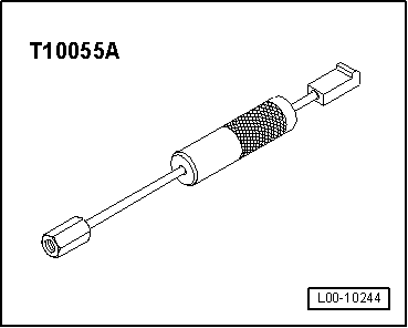
t  Extractor -T10055A-, see equivalent → Anchor
  Note
After removal, the intermediate shaft must always be replaced.
Removing
–  Remove the timing belt from the coolant pump → Chapter.
–  Remove the upper cover of the distribution chain → Chapter.
–  Remove the lower cover of the distribution chain → Chapter.
–  Remove distribution chain → Chapter.
–  Remove the balance shaft chain → Chapter
  L00-10244
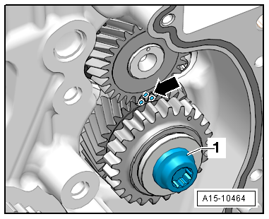
–  Unscrew the bolt -1- and remove the intermediate pinion.
  A15-10464
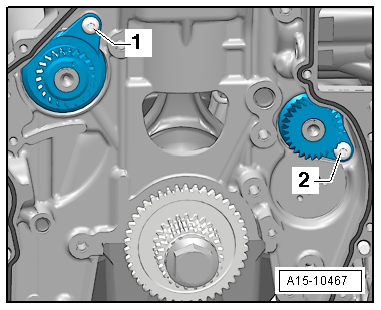
–  Remove the bolt -2- and remove the balance shaft on the intake side.
  A15-10467
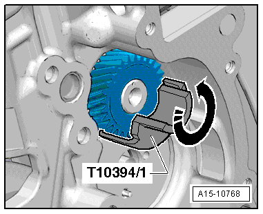
If the intermediate shaft cannot be removed by hand, then use the extractor -T10394-:
–  Apply the shell halves -T10394/1- of the extractor -T10394- and turn upwards in the direction of the arrow.
  A15-10768
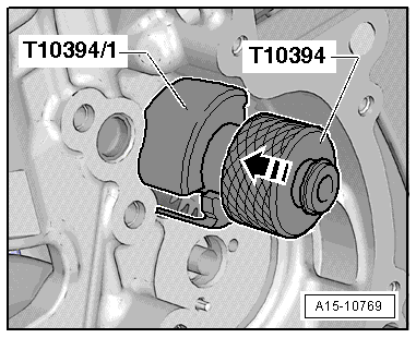
–  Apply the extractor -T10394- and push the mobile sleeve in -the direction of the arrow-.
  A15-10769
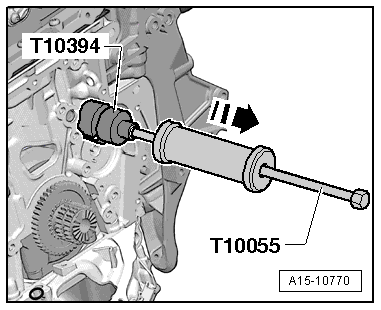
–  Insert the extractor -T10055A- in the extractor -T10394- and press out the idler gear in -the direction of the arrow-.
Fitting
  Note
Due to the reduced play between the idler gear and the cylinder block, the idler gear must be allowed to cool before fitting. Check if the idler gear can be inserted in the cylinder block with ease. If this was not the case, the idler gear must be cooled down before fitting.
l  Tightening torque → Chapter
–  Leave the new idler rod in the freezer shelf for 30 minutes or use a conventional ice spray.
–  Lubricate the balance shaft housing with engine oil.
  A15-10770
–  Mount the new idler gear for the inlet camshaft and tighten the screw -2-.
  A15-10467
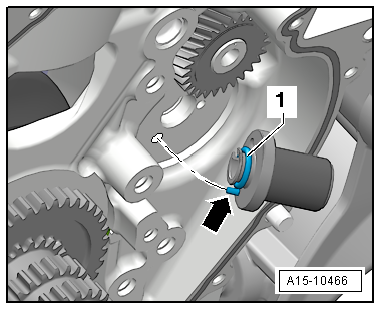
–  Replace O-ring -1- and lubricate with engine oil.
–  Lubricate the socket pin with engine oil and fit it -arrow-; the socket pin must fit into the aperture in the engine block.
  Caution
Always renew idler gear. If this is not done, there is no backlash, which causes engine damage. The new idler gear has a special lubricant coating, which wears off after a short running period and thus automatically creates the specified backlash.
  A15-10466
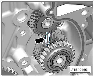
–  Mark faces of gear teeth of idler gear with paint -arrows-.
–  Fit the intermediate pinion; the mark on the balance shaft must be between the marks on the sides of the teeth.
  A15-10465
–  Tighten the bolt -1- of the intermediate pinion: tightening sequence → Fig..
–  Verify the intermediate pinion / balance shaft -arrow- marks.
The remaining installation steps are carried out in the reverse sequence. Note the following:
Fit the balance shaft chain → Chapter.
Fitting the distribution chain → Chapter.
Fit the lower cover of the distribution chain → Chapter.
Install timing chain cover (top) → Chapter.
Install Poly V-belt tension device → Chapter.
Install poly V-belt → Chapter.
Renew oil seal for the coolant pump drive → Chapter.
Fit the timing belt for the coolant pump → Chapter.
  A15-10464

Removing and installing the balance shaft, exhaust side > < Removing and installing the chain of the balance shaft