seat Workshop Repair Guides

SEAT Workshop Service and Repair Manuals

Removing and installing engine > < Technical data
Engine: removing
Engine: removing
  Note
The engine is removed from underneath together with the gearbox.
   
Consult the equivalence table for tools and equipment according to applicability among Seat / VW / Audi / Skoda → Chapter.
Special tools and workshop equipment required
t  Engine support -T10416-with adapters /1, /2, /3, see equivalent → Anchor
t  Torque wrench -VAG 1331-, see equivalent → Anchor.
t  Hydraulic jack -VAG 1383A-, see equivalent → Anchor
t  Engine and gearbox support -VAS 6095-, see equivalent → Anchor
t  Collecting tray -VAS 6208-, see equivalent → Anchor

   
t  Base -VAS 6340-, see equivalent → Anchor
t  Stepladder -VAS 5085-, see equivalent → Anchor
t  Torque wrench -VAG 1332-, see equivalent → Anchor.
t  Centre guide -T10093-, see equivalent → Anchor

  Note
To carry out this work it will be necessary to disconnect battery earth strap. For this purpose, first check whether a coded radio is fitted. Obtain anti-theft coding first if necessary.
   
–  Unbolt the screws -arrows- of the intake air duct and the intake connecting pipe on the exhaust gas turbocharger.
–  Remove vacuum hose -1- under the the intake hose.
  N10-10357
–  Undo the securing bolt -2-.
–  Pull the air filter housing upwards.
–  Disconnect battery → Electrical system; Rep. gr.27
–  Remove battery and battery tray → Electrical system; Rep. gr.27.
–  Open and close the lid of the expansion tank again for releasing the pressure in the cooling system.
–  Drain coolant → Chapter.
–  Observe rules for cleanliness → Chapter.
  N10-10356
–  Remove the fuel supply line -1- and the wire, which leads to the activated carbon container -2-. To do so, press the tabs.
  WARNING
Fuel supply line is pressurised. Wear safety goggles and appropriate clothing to avoid injury and contact with skin. Before loosening hose connections, wrap a cloth around the connection. Then release pressure by carefully pulling hose off connection.
  N10-10317
–  Remove the spring-type hose and the coolant hoses -1- and -2-.
–  Press the retainer -3- beneath the coolant hoses and pull the hose upwards.
–  Move the coolant hoses to the rear.
  N10-10318
–  Remove the coolant hoses on the heat exchanger -arrow-.
  N10-10359
–  Release the coolant hoses -arrow- on the gearbox ends and disconnect.
–  Remove the Lambda probe -G39--1- using Lambda probe open ring spanner set -3337-.
  N10-10321
–  Unscrew the upper securing screw for the alternator -2- and press the alternator slightly downwards.
–  Unscrew the fastening bolts -arrows- and remove the heat shield from the turbocharger.
  N10-10322
–  Unscrew the securing bolts on the exhaust gas turbocharger -arrows-.
  N10-10325
–  Remove the fixing screws -arrows- of the noise insulation.
–  Remove inner front right and left wheel housing moulding → Bodywork, exterior fitting work; Rep. gr.66
  N10-10358
–  Open the spring-type clip -1- on the cooler of the charge-air system.
–  Remove the coolant lines -2- .
–  Open the spring-type hose and remove the coolant hose -1-.
  N10-10360
–  Unplug the connector -2- from the coolant circulation -V50-.
–  Detach the connector -3- of the knock sensor 1 -G61- y -4- of the engine speed sender -G28-.
  N10-10323
–  Disconnect the connector -arrow- from the oil level and temperature sender -G266-.
–  Move the lock carrier in service position: → Bodywork, exterior fitting work; Rep. gr.50
  N10-10364
–  Disconnect the connector -1- for the Lambda probe downstream of the catalytic converter -G130--2-.
  N10-10361
–  Remove securing bolts -1-.
–  Remove the suspension -2- from bolt.
  N10-10362
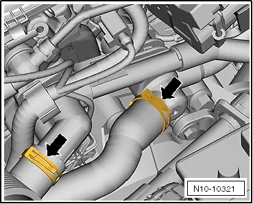
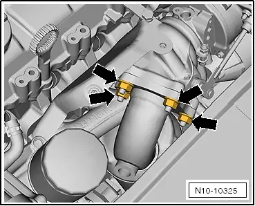
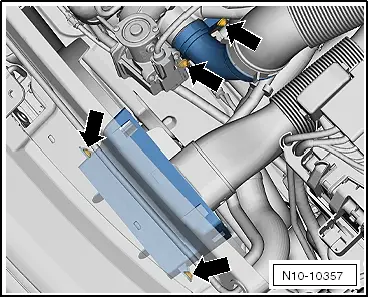
–  Loosen the fixing screws of the clamping sleeve -arrows- and push to rear.
–  Remove the catalytic converter with exhaust pipe downwards.
–  All the cables, that are opened or cut during dismounting, should be placed again in the same location previously occupied during the fitting.
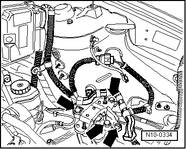
–  Remove all of the electrical cables from the gearbox, alternator, and starter motor leaving them uncovered.
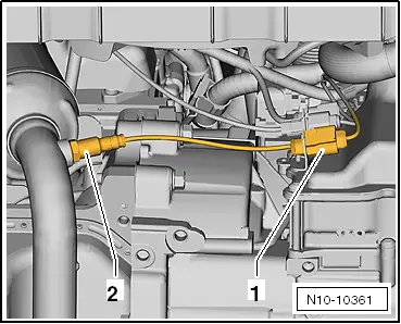
–  Disconnect all other electrical connections as necessary from engine and lay to one side.
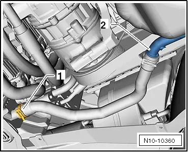
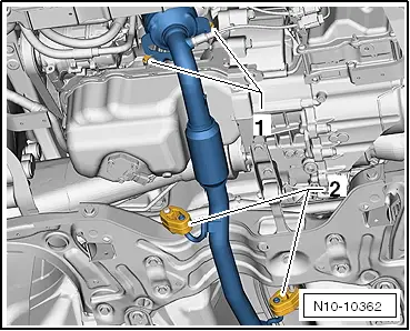
–  Pull vacuum and breather flexible hoses off the engine.
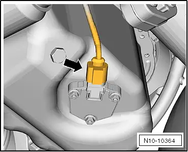
–  Pull connector off thermo-switch and radiator fan.
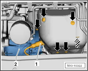
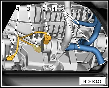
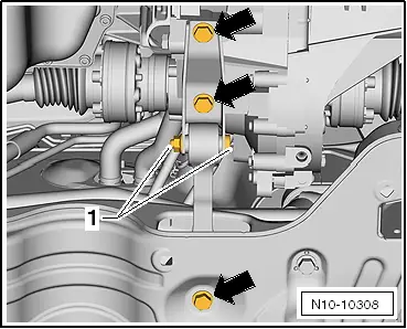
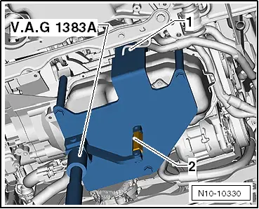
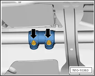
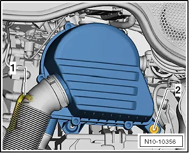
  Caution
Bolt -1- must not be loosened.
  N10-10363
–  Unscrew the fixing bolts -arrows- of the pendulum support.
–  Remove the drive shaft on the right and left from the gearbox and tie up → Running gear, shafts, steering; Rep. gr.40
Vehicles with manual gearbox
–  Remove the gear mechanism from the gearbox: → Rep. gr.34
–  Remove the slave cylinder from the hydraulic clutch: → Rep. gr.30
  Note
Do not depress the clutch pedal.
Vehicles equipped with DSG gearbox
–  Selector lever control cable: removing → Rep. gr.34
Continued for all vehicles
–  Remove poly V-belt → Chapter.
–  Removing air conditioning compressor → Heating, Air conditioning; Rep. gr.87.
  Note
Do not open the air conditioning pipes.
–  Attach the air conditioning compressor to the lock carrier plate.
–  Check that the conducts have not been bent.
  N10-10308
The engine support is required to drain off the engine -T10416-with the gearbox using the adapters -/1-, -/2- and -/3-.
  N10-10328
–  Tighten the adapters -T10416/1- until they make contact with the crank case.
–  Assemble the engine bracket -T10416- using the adapters -/2- and -/3- on the cylinder block.
–  Assemble the engine bracket -T10416- using a screw -1- on the cylinder block and manually tighten it.
  N10-10329
–  Tighten all bolts on the engine bracket -T10416- to 20 Nm.
  Note
Using the adjusting nut -2-, the right angle on the engine support -T10416- between the bolts and the engine and the gearbox jack -V.A.G 1383 A- is adjusted.
–  Mount the engine and gearbox jack -V.A.G 1383 A- to the engine support -T10416-.
–  Lift the engine and gearbox slightly with the engine and gearbox crane -V.A.G 1383 A-.
  Note
To loosen the mounting bolts, use the stepladder -VAS 5085-.
–  Unscrew the earth cable -1-.
  Caution
Nut -2- must not be loosened.
  N10-10330
–  Unscrew the bolts -arrows- that fix the spring mount of the engine.
–  Completely remove the spring mount of the engine.
  N10-10303
–  Unscrew the fixing bolts -arrows- from the gearbox support.
  Note
Carefully guide the unit when lowering to avoid damage.
–  Carefully lower the engine and the gearbox.
  N10-0334

Removing and installing engine > < Technical data