| –
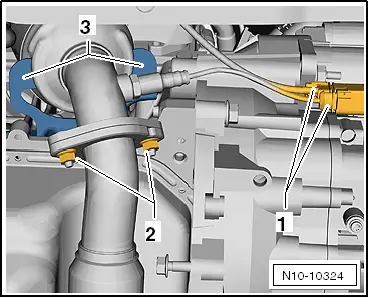
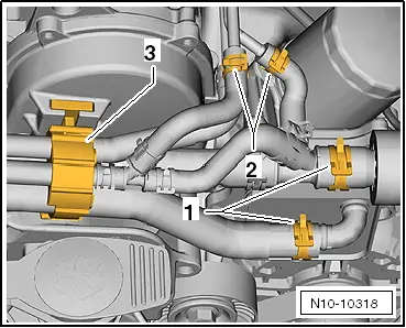
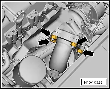
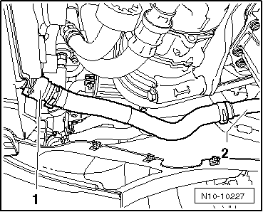
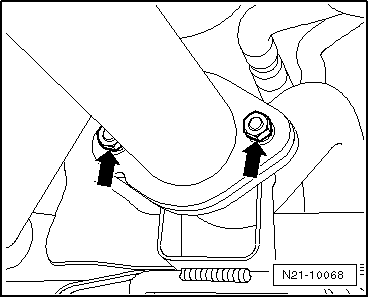
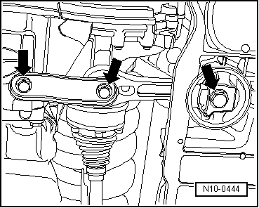
| Unscrew the securing nuts -2- and press the exhaust pipe to the back using an assembly lever in order to remove it from the rubber mountings. |
| –
| Withdraw the exhaust pipe towards the front. |
| –
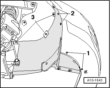
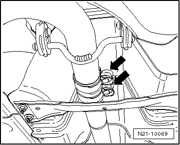
| Undo the securing nuts -3- and remove the catalytic converter downwards. |
| –
| All the cables, that are opened or cut during dismounting, should be placed again in the same location previously occupied during the fitting. |
| –
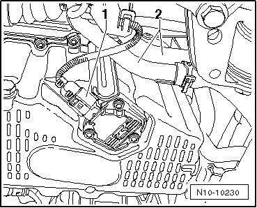
| Remove all of the electrical cables from the gearbox, alternator, and starter motor leaving them uncovered. |
| –
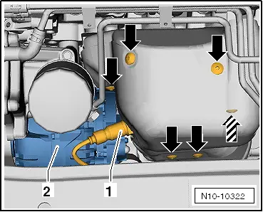
| Pull off or disconnect all other electrical connections as necessary from engine and lay to side. |
| –
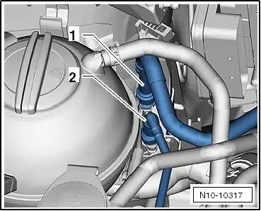
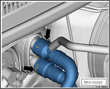
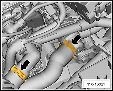
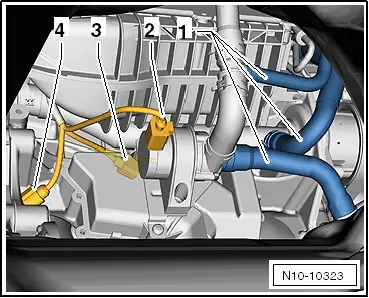
| Pull vacuum and breather hoses off engine. |
| –
| Pull connector off thermo-switch and radiator fan. |
|
|
|

 Note
Note
 WARNING
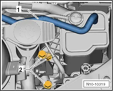
 Caution