seat Workshop Repair Guides

SEAT Workshop Service and Repair Manuals

Engine lubrication > < Valve control: repairs
Distribution timing: adjustment
   
Distribution timing: adjustment
Consult the equivalence table for tools and equipment according to applicability among Seat / VW / Audi / Skoda → Chapter.
Special tools and workshop equipment required
t  Camshaft clamp -T10414-, see equivalent → Anchor.
t  Fastening screw -T10340-, please see Correspondence → Anchor
t  Torque wrench -VAS 6583-, see equivalent → Anchor.
t  Torque wrench -VAG 1332-, see equivalent → Anchor.
t  Engine and gearbox support -T10172-, see equivalent → Anchor
t  Base -VAS 6340-, see equivalent → Anchor

   
t  Extractor -T10118-, see equivalent → Anchor
t  D 176,600 A1 Sealing compound
t  2 head studs M6 x 70 (e.g. screws without head)
  W00-1148
Operation process
–  Drain coolant → Chapter.
–  Remove the spring-type hose and the coolant hoses -1- and -2-.
–  Press the retainer -3- beneath the coolant hoses and pull the hose upwards.
–  Move the coolant hoses to the rear.
  N10-10318
–  Remove the two hoses -1- from the non-return valve.
–  Remove the attachment bolts -2- and the non-return valve from the cylinder head cover.
  N13-10382
–  Unscrew all attachment bolts from the cover of the distribution housing -1-.
–  Remove the cover of the distribution housing.
  N13-10390
–  Unscrew the bolts -1- and disconnect the retainer of the coolant hose -2-.
  N13-10385
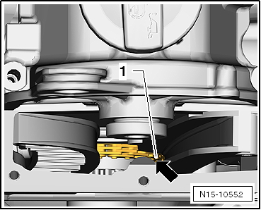
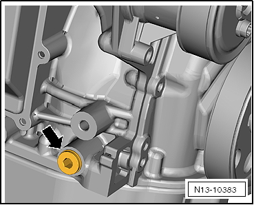
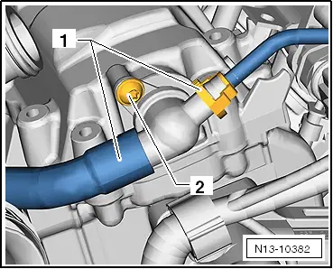
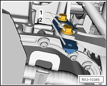
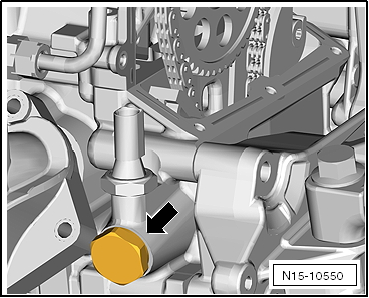
–  Unscrew the sealing plug -arrow- from the cylinder block.
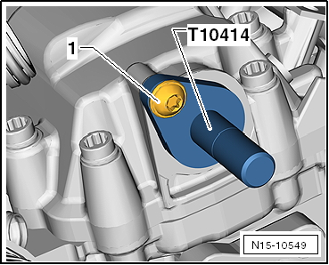
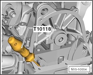
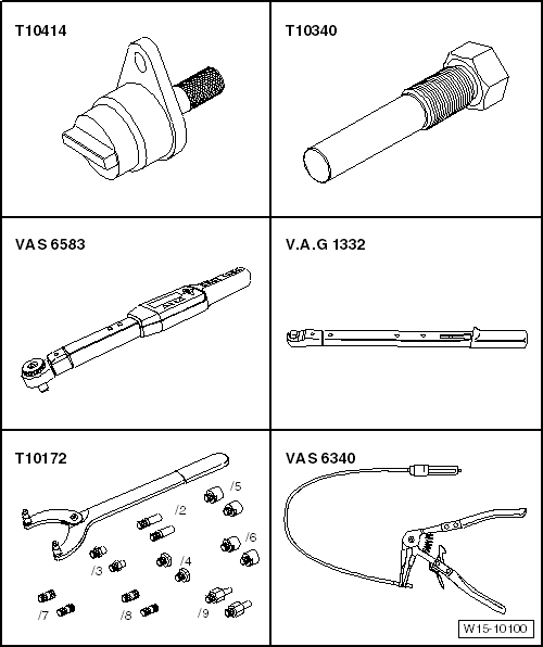
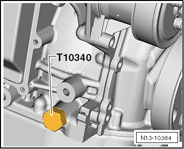
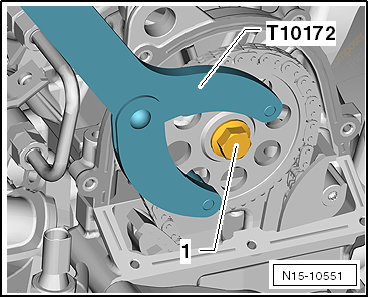
–  Screw in the locking bolt -T10340- to the end of the cylinder block.
  Caution
If the locking bolt -T10340- cannot be screwed until the end point, the crankshaft is not in the right position.
In this case, proceed as follows:
–  Remove the locking pin.
–  Turn the crankshaft by a 1/4 90° rotation in the direction of the operation of the engine.
–  Tighten the securing screw -T10340- until the end point in the crankshaft sump.
–  Tighten the securing bolts securing bolts -T10340- to 30 Nm.
–  Turn the crankshaft to the end point in the direction of the operation of the engine.
  N13-10383
Use the securing screw -T10340- to immobilise the crankshaft in the direction of operation of the engine.
–  Remove sump → Chapter.
  N13-10384
–  Remove the oil pump cover -1-.
  N15-10556
–  Unscrew the chain tensioner for drive chain -arrow-.
  N15-10550
–  Slacken the camshaft securing bolt -1-.
–  Immobilise the camshaft wheel using the counterhold tool -T10172-.
–  Remove the camshaft wheel from the securing bolt.
  N15-10551
–  Assemble the timing chains -1- located on the cast iron nose -arrow- of the control housing.
  Note
The cast iron nose on the interior of the control housing prevents the control housing from falling down.
  N15-10552
–  Fit the camshaft wheel -1- to the camshaft and tighten the attachment bolt -2- to 50 Nm.
  Note
The camshaft sprocket must be tightened to 50 Nm in order to allow the camshaft to rotate as described in the following.
–  Immobilise the camshaft wheel using the counterhold tool -T10172-.
–  Turn the crankshaft by a 1/4 90° rotation in the opposite direction of the operation of the engine.
  Note
Turning the crankshaft against the direction of the engine rotation prevents damage being caused to the valves in the subsequent adjustment of the camshaft.
  N15-10553
–  The camshaft rotates until the grooves are in the positions shown -arrows-.
  N13-10381
–  Insert the camshaft fastener -T10414- up to the end of the cylinder head cover.
–  Hand-tighten bolt -1-.
–  Turn the crankshaft to the end point in the direction of the operation of the engine.
–  Remove the camshaft sprocket.
–  Immobilise the camshaft wheel using the counterhold tool -T10172-.
  N15-10549
–  Lift the timing chains with the assembly tool -T10118-.
  N15-10554
–  Check the correct position of the timing chains -1- on the crankshaft gear from below.
  N15-10557
–  Fit the timing chains -1- on the pinion -2-.
The timing chain must be in the section of the guide rail -3- and be slightly taut.
–  Tighten the new securing bolt by hand.
The distribution chain must run across the centre of the tensioning rail.
  N15-10555
–  Tighten the chain tensioner to 60 Nm.-arrow-.
  N15-10550
–  Tighten the camshaft sprocket with a new securing bolt -arrow 1- to 50 Nm.
  Note
The securing bolt is rotated another 1/4 90° after checking the valve timing at the end of the process.
–  Immobilise the camshaft wheel using the counterhold tool -T10172-.
–  Remove the camshaft clamp -T10414- from the camshaft.
–  Unscrew the locking bolt -T10340- from the cylinder block.
–  Turn the crankshaft in the direction of engine by 2 rotations.
–  Tighten the securing screw -T10340- until the end point in the crankshaft sump.
–  Turn the crankshaft to the end point in the direction of the operation of the engine.
If the camshaft fastener -T10414- can be fitted to the camshaft, the control timings are correct.
If the control timings are not correct:
–  Repeat the valve timing adjustment once more .
  N15-10551
–  Rotate the securing bolt another -1-1/4 turn (90°).
–  Immobilise the camshaft wheel using the counterhold tool -T10172-.
–  Remove the camshaft fastener -T10414- and the locking bolt -T10340-.
–  Fit the upper valve timing housing → Chapter.
  N15-10551
–  Assemble the non-return valve. Tightening torque of the fastening bolts -2-: 8 Nm
–  Connect the hoses -1-.
–  Install sump → Chapter.
  N13-10382
–  Assemble the sealing plug. Tightening torque: 30 Nm
–  Fill up coolant → Chapter.
Further assembly is basically the reverse of the dismantling sequence.
  N13-10383

Engine lubrication > < Valve control: repairs