
Leon Mk1
| Assembly overview |

| 1 - | 50 Nm + turn 90° further |
| q | Renew. |
| 2 - | Camshaft pulley |
| q | Check the position on fitting the distribution chain |
| 3 - | 10 Nm |
| 4 - | Hall sender -G40- |
| q | With O-ring. |
| q | Renew O-ring if damaged. |
| q | removing and installing → Chapter |
| 5 - | Cylinder head cover: |
 Caution
|
| q | removing and installing → Chapter |
| q | Remove any sealant remains. |
| q | Before installing, apply the sealants D 189 500 A1 and D 154 103 A1 |
| q | When installing fit vertically from above onto studs and dowel pins |
| 6 - | Non-return valve |
 Note
Note| The O-rings are not available as a separate spare part. |
| 7 - | 10 Nm |
| 8 - | O-ring |
Note| The O-rings are not available as a separate spare part. |
| q | Replace the O-rings of the check valve in event of wear |
| q | Before mounting, lightly grease with engine oil |
| 9 - | Camshaft: |
| q | removing and installing → Chapter |
| q | Checking axial clearance → Chapter. |
| q | Apply oil before fitting (also axial bearing collar) |
| 10 - | Valve cotters |
| 11 - | Valve spring plate |
| 12 - | Valve stem oil seal |
| q | Renew. |
| 13 - | Valve spring |
| q | With removed cylinder head, remove and install the assembly device for valves -2036- and the valve lever -VW 541/1A-. |
| q | With cylinder head installed → Chapter. |
| 14 - | Valve guide |
| q | checking → Chapter |
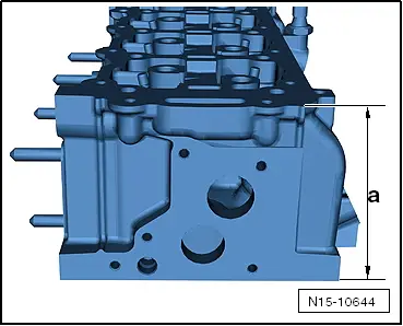
| 15 - | Cylinder head |
| q | removing and installing → Chapter |
| q | Reworking valve seats → Chapter. |
| q | Reworking sealing surface → Fig.. |
| 16 - | Valves |
| q | Do not rework. Only lapping in is permitted. |
| q | Valve dimensions → Fig. |
| 17 - | Locking nut, 15 Nm |
| 18 - | Oil seal |
| q | Renew. |
| 19 - | Dowel pins |
| 20 - | 8 Nm |
| q | Observe the correct tightening order |
| q | removing and installing → Chapter |
| 21 - | Retaining frame |
| q | For camshaft |
| q | removing and installing → Chapter |
Note
|
|