| –
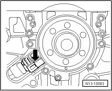
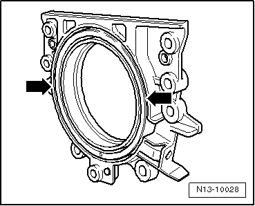
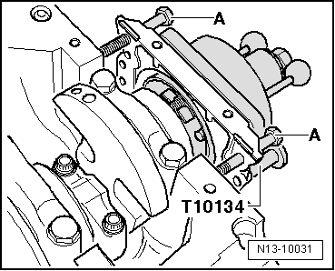
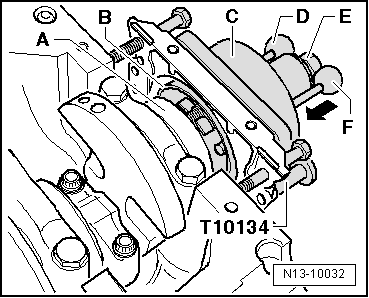
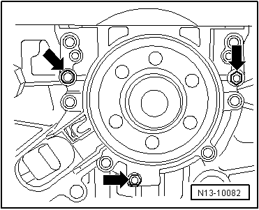
| Screw the three bolts M6 x 35 mm into the threaded holes of the sealing flange-arrows-. |
| –
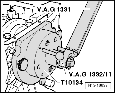
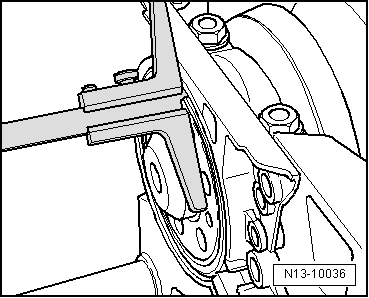
| Screw the screws into the sealing flange in diagonal pairs (max. 180° per screw) and drive the sealing flange together with the wheel sender away from the crankshaft. |
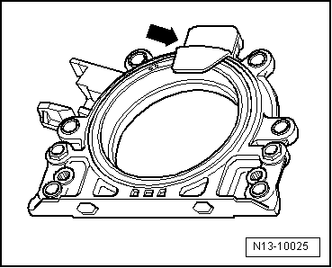
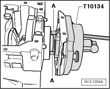
| To remove the sealing flange with the integrated sender wheel to the crankshaft |

Note | t
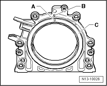
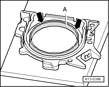
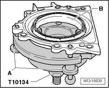
| The sealing flange with a PTFE seal is equipped with a sealing lip support ring. This support ring acts as an assembly sleeve and must not be removed before installation. |
| t
| Once unwrapped, do not separate the sealing flange and the sender wheel or modify the position. |
| t
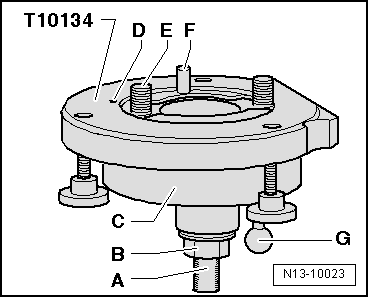
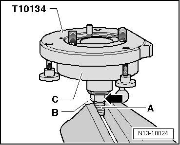
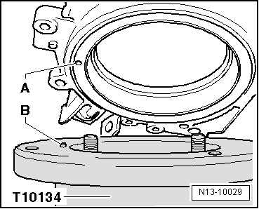
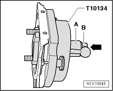
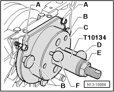
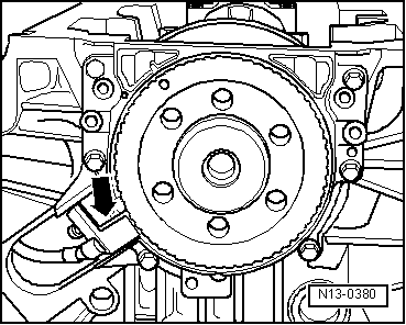
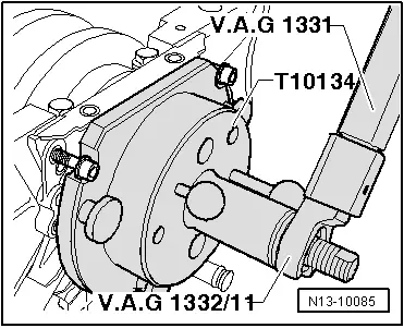
| The sender wheel finds its position when fitted to the position pin of the fitting device -T10134-. |
| t
| The sealing flange and the seal make up one inseparable component and can only be replaced along with the sender wheel. |
| t
| The position of the centre guide -T10134- with respect to the crankshaft is determined by a guide pin inserted in a borehole in the crankshaft. |
|
|
|