
Leon Mk1
 Note
Note
Note
|
|
|
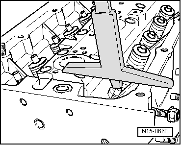
- | Distance measured Minimum distance | 8,0 7,6 | mm mm | |
| = | max. perm. rework dimension → Remark | 0,4 | mm | |
|
|
|
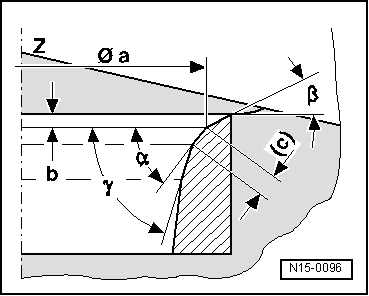
| a b c Z α β γ | = Ø 28.7 mm = Max. permissible reworking dimension 1 = 1.5 ... 1.8 mm = lower edge of cylinder head = 45° valve seat angle = 30° higher angle of correction = 60° lower angle of correction |
|
| a b c Z α β γ | = Ø 25.0 mm = maximum permitted reworking dimension 1 = approx. 1.8 mm = cylinder head lower edge = 45° valve seat angle = 30° upper correction angle = 60° lower correction angle |
|