seat Workshop Repair Guides

SEAT Workshop Service and Repair Manuals

Air filter > < Charge air system
Checking fuel pressure sender
Special tools and workshop equipment required
   
t  Assembly tool -T10118-
t  "Socket wrench insert, double hexagon 1/2“, 27 mm" -VAS 5301/7-
t  Digital pressure gauge -VAS 6394/1-
t  Adapter for the testing functions -VAS 5570-
  WARNING
The injection system is sub-divided into a high pressure system (max. approx. 120 bar) and a low pressure system (approx. 6 bar).
Prior to opening the high-pressure area, e.g. when removing the high-pressure pump, fuel rail, injectors, a fuel line, or the fuel pressure sender -G247-, the fuel pressure in the high-pressure area must be reduced to a residual pressure of approx. 6 bar. The appropriate procedure is described in the chapter on releasing pressure in the high-pressure section → Chapter.
Operation process
  W00-1148
–  Lift off engine cover panel at points -1- and pull it forwards in direction of -arrow-.
–  Remove air filter → Chapter.
  N10-10281
–  Remove fuel pressure sender -G247--1-.
  N24-10492
–  Instead of fuel pressure sender -G247-, screw in adapter -VAS 6394/2- and tighten to 22 Nm.
  N24-10493
–  Open cover -2- of digital pressure gauge -VAS 6394/1- and tighten fuel pressure sender -G247- to digital pressure gauge to 22 Nm.
–  Screw pressure line -1- of digital pressure gauge -VAS 6394/2- hand-tight to adapter -VAS 6394/1-.
  N24-10400
–  Connect test adapter -VAS 5570- between fuel pressure sender -G247--1- and connector.
  N24-10494
–  Connect vehicle diagnosis, testing and information system -VAS 5051B--1- as follows:
–  Push diagnostic cable connector -2- onto diagnostic connection in driver footwell.
–  Switch on ignition.
–  Press following keys on display in succession:
Vehicle self-diagnosis
01 - Engine electronics
011 - Measured values
–  There, enter 140 and acknowledge with Q.
Display field 2 shows the nominal value; display field 3 shows the actual value reported to the vehicle by the fuel pressure sender -G247-.
  N01-0590
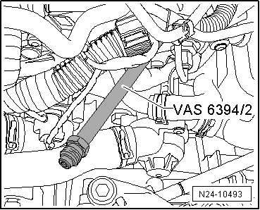
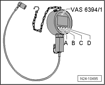
–  Switch on digital pressure gauge -VAS 6394/1- by pressing key -A- briefly once.
  Note
When button -A- is pressed for 2 seconds, the illumination will be switched on for 20 seconds.
Digital pressure gauge -VAS 6394/1- should display 0 bar; if this is not the case, press key -C- briefly once for zero point compensation.
–  Start engine.
–  Compare pressure displayed by digital pressure gauge -VAS 6394/1- with actual value of vehicle diagnosis, testing and information system -VAS 5051B-.
The pressures may deviate by up to 5 bar.
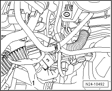
If pressures do not correspond, fuel pressure sender -G247- must be renewed.
  WARNING
The injection system is sub-divided into a high pressure system (max. approx. 120 bar) and a low pressure system (approx. 6 bar).
Prior to opening the high-pressure area, e.g. when removing the high-pressure pump, fuel rail, injectors, a fuel line, or the fuel pressure sender -G247-, the fuel pressure in the high-pressure area must be reduced to a residual pressure of approx. 6 bar. The appropriate procedure is described in the chapter on releasing pressure in the high-pressure section → Chapter.
  Note
Once the high-pressure in the high-pressure area is reduced, open the system immediately as the pressure will rise again due to warming.
–  Renew fuel pressure sender -G247- and again compare both measured values.
If measured values again fail to correspond:
–  Check wiring → Vehicle diagnostic tester.
If measured values correspond:
–  Further testing is carried out with „Guided Fault Finding“ → Vehicle diagnostic tester.
  N24-10495

Air filter > < Charge air system