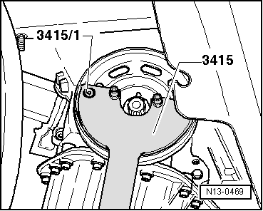
seat Workshop Repair Guides

SEAT Workshop Service and Repair Manuals

Removing and installing ancillary bracket > < Poly-V belt routing
Distribution housing: removing and fitting
   
Distribution housing: removing and fitting
Special tools and workshop equipment required
t  Support bracket -10 - 222 A-
t  Rack -10 - 222 A /1-
t  Counterhold tool -3415-
t  Pin -3415/1-
t  Torque wrench (5... 50 Nm) -V.A.G 1331-

   
t  Adapters -10 - 222 A /28-
t  To avoid damaging wing edges, apply adhesive tape -arrow- to bottom areas of both adapters -10 - 222 A /28-.
  N34-11564
t  Torque wrench (40... 200 Nm) -V.A.G 1332-
t  Sealant D 176 501 A1
Removal:
–  Remove engine splash guard or noise insulation → General body repairs, exterior; Rep. gr.50.
–  Remove the front right-hand wheel well moulding: → General body repairs; Rep. gr.66
–  Remove air filter → Chapter.
–  Mark direction of rotation of poly V-belt and remove it → Chapter.
  W00-0428
Vehicles with air conditioner
–  Remove air conditioner compressor from bracket with refrigerant lines still connected → Heating, air conditioning; Rep. gr.87.
  Note
t  The air conditioning system lines must not be opened.
t  Observe additional information → Chapter.
–  Release and remove electrical connector -1- for air conditioner compressor regulating valve -N280- from air conditioner compressor.
–  Remove bolts -arrows- for air conditioner compressor.
–  Tie up air conditioner compressor together with refrigerant hoses to body.
All other vehicles continued
–  Remove alternator → Electrical system; Rep. gr.27.
–  Remove expanded plastic components or seals in area of wing edges.
  A10-1637
–  Remove plenum chamber cover -1- in exterior area → Body - front; Rep. gr.50.
–  Place support bracket -10 - 222 A- with adapter -10 - 222 A /8- behind bonnet stay.

–  Place adapter -10 - 222 A /8- behind bend -2-.
  Note
Plenum chamber cover is in contact with adapters -10 - 222 A /8-.
–  Hook support bracket -10-222 A- into suspension eyes.
   
–  Detach brackets -2- from the low pressure valve in the -direction of the arrow-.
  Note
Disregard item -3-.
–  Undo screws -1- of the low pressure valve and remove the valve from the controller housing.
  E24-10077
–  Disconnect connector -1-.
–  Unscrew the fixing screws -3- and place the expansion tank aside without removing the coolant hoses.
  N10-10518
–  Unscrew the nut -1- and expose the earth cable.
–  Take up weight of engine and remove bolts -arrows-.
–  Remove coolant pump belt pulley → Chapter.
–  Remove sump → Chapter.
  N10-10303
–  Loosen pulley securing bolt. Hold belt pulley with counterhold -3415- and -3415/1-.
  N13-0469
–  Undo socket bolts of valve timing housing.
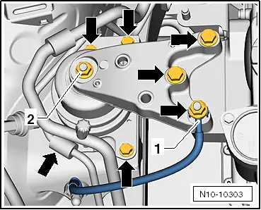
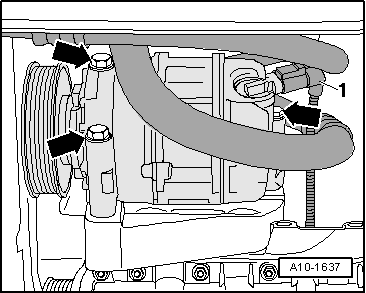
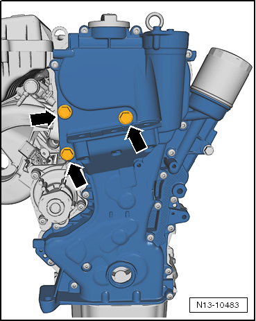
–  Undo the marked socket bolts -arrows-.
–  Remove distribution chain.
  Note
Crankshaft bearing bush remains in sealing flange.
Installation
Installation is in the reverse sequence of removal. Note the following:
  Note
The pulley contact surfaces, securing bolt, bearing bush and crankshaft chain sprocket must be free of oil and grease.
–  Clean sealing surfaces carefully. They must be free of oil and grease.
  Note
t  The valve timing housing is still sealed to the engine with a seal and also sealant D 176 501 A1.
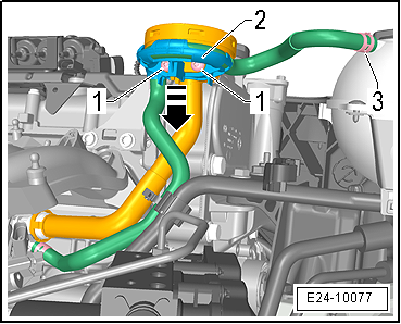
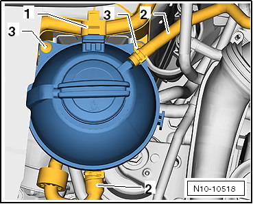
t  
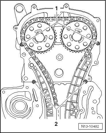
The sealant D 176 501 A1 is used to prevent leaks between the valve timing housing and the joints -1- and -2-.
t  The sealant point must have a diameter of 10 mm and a thickness of approx. 1 mm.
t  Do not apply sealant until directly before the valve timing housing is fitted.
  N13-10483
–  Apply sealant D 176 501 A1 to the joints camshaft housing/cylinder head -1- and cylinder head/cylinder block -2-.
Renewing crankshaft oil seal, belt pulley end → Chapter.
–  Fit new gasket onto dowel pins.
–  Screw two -M6x80- studs into cylinder head and cylinder block to improve guidance.
–  Fit timing case with crankshaft bearing bush simultaneously onto studs, dowel pins and crankshaft journal.
–  Tighten valve timing housing securing bolts evenly and diagonally.
Take care not to tilt the camshaft housing.
Tighten securing bolts.
–  Install the low pressure valve into the controller housing.
  N13-10482
Tightening torque:
ComponentTightening torque
Bolt M610 Nm
Bolt M1050 Nm
Air conditioner compressor to bracket23 Nm
Vacuum valve 10 Nm
V-belt pulley → Chapter
Engine mounting 1.6l petrol engine → Chapter
Coolant pump belt pulley → Chapter
Oil pan → Chapter


Removing and installing ancillary bracket > < Poly-V belt routing