
Leon Mk1
|
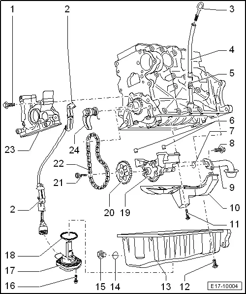
| 1 - | 15 Nm |
| 2 - | Retainer |
| q | Wiring harness for the oil level and oil temperature sender -G266- |
| 3 - | Oil dipstick |
| q | The oil level must not be above the MAX mark. - Risk of damage to the catalytic converter! |
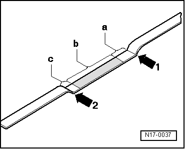
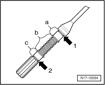
| q | Dip stick marks → Fig. |
| 4 - | Filling funnel |
| q | Remove and evacuate the oil by absorption |
| 5 - | Guide pipe |
| 6 - | Dowel sleeves |
| 7 - | O ring |
| q | Renew |
| 8 - | 15 Nm |
| 9 - | Suction line |
| q | Clean strainer if soiled. |
| 10 - | Baffle plate |
| 11 - | 15 Nm |
| 12 - | 15 Nm |
| 13 - | Oil sump |
| q | Clean sealing surface before fitting. |
| q | Removing and fitting → Chapter |
| 14 - | Seal |
| q | Renew |
| 15 - | Oil drain plug, 30 Nm |
| q | With permanent oil seal |
| q | Renew |
| 16 - | 10 Nm |
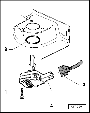
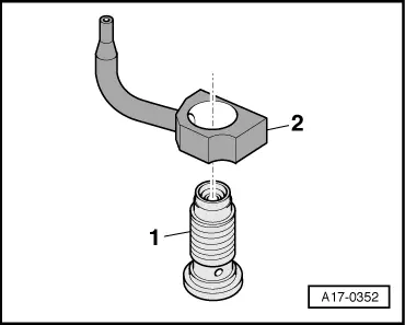
| 17 - | Oil level/oil temperature sender -G266- |
| q | Depending on design |
| q | Removing and fitting → Fig. |
| q | Checking: → Vehicle diagnostic, testing and information system VAS 5051 |
| 18 - | O ring |
| q | Renew |
| q | Grease before assembly. |
| 19 - | Oil pump: |
| q | For pressure relief valve, approx. 12 bar |
| q | Removing and fitting → Chapter |
| q | Before fitting check that the dowel pegs are fitted → Item |
| q | Replace if there is scoring on the friction surfaces or the gear teeth. |
| q | Tightening torque for oil pump cover to oil pump housing: 10 Nm |
| 20 - | Oil pump chain sprocket: |
| q | Note fitting position: |
| q | Sprocket can only be fitted on oil pump shaft in one position. |
| q | Oil pump chain sprocket: Removing and installing → Chapter |
| 21 - | 20 Nm + 90° (1/4 turn) |
| q | Renew |
| 22 - | Chain for oil pump |
| q | Make a coloured marking for the direction of rotation with before removing |
| q | Check for wear. |
| 23 - | Front sealing flange: |
| q | Must be housed correctly in the dowel sleeves for adjusting |
| q | Removing and fitting → Chapter |
| q | Crankshaft oil seal, pulley end: Renew → Chapter |
| 24 - | Chain tension device with tensor rail, 15 Nm |
| q | Do not dismantle. |
| q | Note fitting position: |
| q | Pre-tension spring and engage before installing |
|
|
|
|
|
|