seat Workshop Repair Guides

SEAT Workshop Service and Repair Manuals

Injection system > < Components and functions
Voltage supply to the engine control unit: verification
   
Voltage supply to the engine control unit: verification
Special tools and workshop equipment required
t  Hand multimeter -V.A.G 1526A- oder multimeter -V.A.G 1715-
t  Auxiliary measurement tool set -V.A.G 1594A- or -V.A.G 1594C-
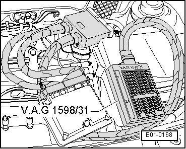
t  Double connection engine testing unit -V.A.G 1598/31- (AZL engines) or -V.A.G 1598/22- (BBX engines)
t  Current flow diagrams

Test conditions
l  The fuses must be OK.
l  Battery voltage must be at least 11.5 V.
l  All consumer electrics should be connected, for example: the lights and the heated rear window.
l  Vehicles fitted with air conditioning must have it disconnected
l  Alternator OK.
Verification process
   
–  Connect test box -V.A.G 1598/31- to control unit wiring harness, without connecting the engine control unit (for BBX engines use the tester -V.A.G 1598/22-) → Chapter.
  Note!
t  The voltage supply for the positive terminal of the engine control unit is made on the contact 3 (terminal 15) and on the contact 62 (terminal 30) for AZL engines and contact 5 (terminal 15) and contact 15 (terminal 30) for BBX engines.
t  The connection of the earth for the engine control unit is made on the contacts 1 and 2 for the AZL engines and contacts 2 and 28 for BBX engines.
–  Measure the voltage with the multimeter and the auxiliary cables of -V.A.G 1594 A- or -V.A.G 1594 C- as follows:
  E01-0168
Test box -V.A.G 1598/31-,
test box socket
Test box -V.A.G 1598/22-,
female connector
Measure to
12Battery positive
228Battery positive
6215Engine ground
 Specification: about the battery voltage

Vehicles with engine identification letters AZL
–  Connect the engine control unit to the engine testing equipment -V.A.G 1594/31-.
–  Turn the ignition on.
   
Test box -V.A.G 1598/31-,
female connector
Measure to
3Engine ground
121 → NoteEngine ground

1)  After disconnecting the ignition, the current supply relay for Motronic -J271- will still supply current to terminal 121 of the engine control unit for a maximum of 15 minutes. Specification: about the battery voltage.
–  Switch ignition off.
Continue for all vehicles
If the specifications are not attained:
–  Check wiring connections to relay plate according to current flow diagram: → Current flow diagrams, Electrical fault finding and Fitting locations.
–  Verification of the current supply relay for the Motronic -J271- → Chapter.
   

Injection system > < Components and functions