seat Workshop Repair Guides

SEAT Workshop Service and Repair Manuals

Engine control unit > < Data bus: verification
Activation: verification
Test conditions
l  Injector resistance, OK.
Verification process
–  Pull off connectors from all the injectors.
   
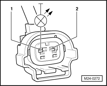
–  Connect diode test lamp -V.A.G 1527 B- to contacts of the injector connector being checked.
  Note!
Use test probes -V.A.G 1594 A- or -V.A.G 1594 C- if the vehicle has sealed connectors.
–  Operate the starter motor (while doing this the engine may start) and check the activation of the injector.
The LED must flicker.
  Note!
The voltage testers with a low current absorption do not extinguish completely during the activation of the engine control unit, they stay shining weakly, increasing their intensity when activated.
The LED does not flicker:
  M24-0272
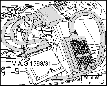
–  Connect test box -V.A.G 1598/31- to control unit wiring harness, without connecting the engine control unit (for BBX engines use the tester -V.A.G 1598/22-) → Chapter.
  E01-0168
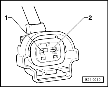
–  Check the wiring between test box and 2-pin connectors of injectors, using current flow diagram.
  E24-0219
Cyl.Injector connector,
contact
Test box -V.A.G 1598/31-,
test box socket
Test box -V.A.G 1598/22-,
test box socket
129679
229759
328873
428965
Specification: 1.5 Ω max. 

–  Additionally check wires for short to one another.
If there is no fault in the wiring and the resistance measurement values are OK.:
–  Replace engine control unit: → VAS 5051; Vehicle self-diagnosis.
   

Engine control unit > < Data bus: verification