| t
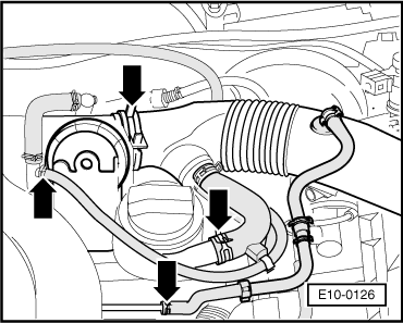
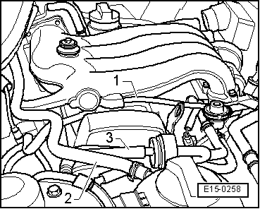
| The fuel pressure regulation flexible low pressure tube -1-. |
| t
| The coolant flexible tubing -2- from the expansion tank. |
| t
| The flexible tube -3- from the solenoid valve for the active carbon system deposit. |
| The flexible coolant tube -2-, the flexible tube -3-, and the low pressure tube for the brake servo, are secured to the upper part of the inlet manifold. |
| –
| For vehicles with the engine identification letters AZL, remove the bolts attaching the inlet manifold to its support by the rear. |
| Vehicles with engine identification letters BBX |
| –
| Separate the connecter for the pressure sender on the upper part of the inlet manifold. |
| –
| Remove the connection for the lambda probe -G39- from its attachment to the inlet manifold. |
| –
| Remove the filling funnel from the dip stick. |
| Continue for all vehicles |
| –
| Remove the front bolts attaching the upper and lower parts of the inlet manifold. |

Note! | For vehicles with the engine identification letters BBX, the upper part of the inlet manifold is attached to its support using two rubber caps. To separate the inlet manifold from its support, gently lever using a screwdriver. |
| –
| Remove the upper part of the inlet manifold. |
| –
| Cover using a clean lint-free cloth, the admission tubes for the lower inlet manifold elements. |
| Lower part of inlet manifold: |
| l
| Vehicles with engine identification letters AZL → Item. |
| l
| Vehicles with engine identification letters BBX → Item. |
|
|
|