seat Workshop Repair Guides

SEAT Workshop Service and Repair Manuals

Engine lubrication > < Servicing valve gear
Removing and installing cylinder head
t  Removing → Anchor
t  Installing → Anchor
   
Special tools and workshop equipment required
t  Counterhold tool -T20018B-
t  Extractor -T20119A-
t  Tray -T20173-
t  attachment tool -T20174-
t  Extractor -T40039-

Removing
  Note
t  All cable clamps that become loose or cut when removing must be re-installed in the same place when installing.
t  Carry out an engine oil change if this is dirty → Booklet1.
t  When using sealing products, follow current recommendations → ETKA (electronic parts catalogue).
t  Before starting to dismount the cylinder head, the fuel system pressure should be reduced. It is important to follow the procedure for reducing pressure → Chapter.
–  In vehicles equipped with a radio or radio and coded navigation system (RNS), the code should be observed, obtaining the code where necessary.
   
–  Detach engine cover -arrows-.
  WARNING
Hot vapour/hot coolant may escape when opening expansion tank. Cover cap with cloth and open carefully.
–  Open cap on coolant expansion tank.
  E10-10017
–  In the versions with rigid battery protection, remove the cover -1-; press the release tab -arrow- to do so.
  WARNING
Note the precautionary instructions for disconnecting the battery → Electrical system; Rep. gr.27.
  A10-1611
–  With ignition switched off, disconnect earth cable -arrow- at battery.
  A10-1612
–  Remove central soundproofing -Anchorage points 1 ... 3-.
–  Place the Drip tray -T20173- under engine.
  A10-1565
For engines with identification letters BLR and BLY
–  Turn drain plug -arrow- on radiator anti-clockwise, if necessary fit drain hose to connection.
  A10-0118
For engines with identification letters BVY and BVZ
Release the quick connection -arrow-, and remove the coolant hose from the radiator.
  N19-0276
Continue for all engines
–  Disconnect the connector -1- of the oil pressure sender -F1-.
–  Additionally take coolant hose on lower part of oil cooler off -2- and drain off remaining coolant.
  Note
The vibration shock absorbing elements in the front exhaust pipe must not be bent more than 10° - otherwise they can be damaged.
  A19-0391
–  Remove securing nuts -arrows- for exhaust manifold to front exhaust pipe.
  N10-10085
–  Unbolt the exhaust system bracket -arrows-.
  A10-1632
–  Remove bolt -3-.
–  Loosen bolts -1- and -2- of the exhaust manifold bracket.
  A26-0712
–  Dismount the exhaust manifold bracket -arrows-.
  A13-0571
For engines with identification letters BLR and BVY
–  Remove the connectors -1- and -2- of the lambda probes in front of the catalytic converter of the support and disconnect them. (The number of connectors may vary depending on version).
  A10-1614
–  Disconnect the connector -2- and the coolant hoses -1- from the exhaust gas recirculation valve.
  E26-10013
Continue for all engines
–  Disconnect coolant hose -arrow-.
  WARNING
Fuel system is under pressure! Before opening the system place a cloth around the connection. Then release pressure by carefully pulling fuel hose from connection. Wear safety goggles and appropriate clothing to avoid injury and contact with skin.
  A10-1618
–  Disconnect the hose to the active carbon filter -1-.
–  Remove the fuel supply tube -2-.
–  Remove poly V-belt → Chapter.
–  Remove the counterhold -T20167- from the Poly-V tension device.
–  Removing notched belt:
   removing and fitting; vehicles without separated notched belt guard → Chapter
   Removing and installing the toothed belt; vehicles without separated toothed belt guard → Chapter
  E10-10020
–  Disconnect the connector from the Hall sender -G40-.
–  Remove the intake manifold → Chapter and the fuel rail → Chapter.
  A15-0761
–  Unplug connectors from injectors-arrows-.
  A15-0762
–  Remove 8-contact connector from the injectors -1-.
–  Unscrew earth connection -2-.
–  Pull out the plug -3-.
–  Pull out the plug -4-.
  A13-0561
–  Pull all of the ignition coils out about 30 mm using the extractor -T40039-.
  N28-10011
–  Release the connectors -2- and separate the ignition coils at the same time.
–  Disconnect the breather hose -1- from the crankshaft sump on the cylinder head cover.
–  Remove all the ignition coils with output stages -2- using the extractor -T40039-.
  A15-0700
–  Disconnect connector -2- from Valve -1- for variable distribution -N205-.
  A24-0790
–  Release the cylinder head cover from the outside towards the inside ( in reverse order to that shown in the figure)
–  Now remove the cylinder head cover.
  N15-10047
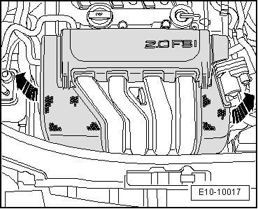
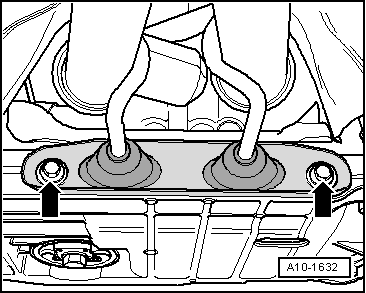
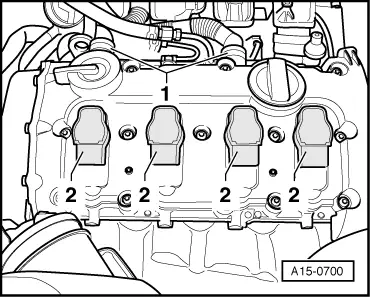
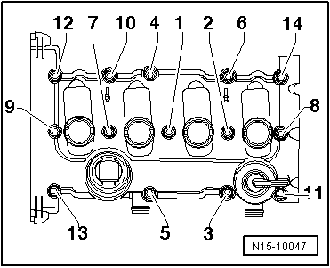
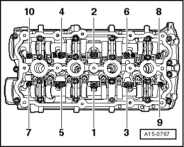
–  Separate the cylinder head fastening bolts, following the order of loosening shown in the figure.
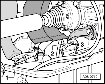
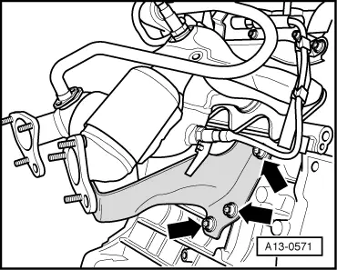
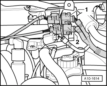
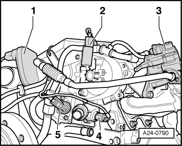
  Note
Ensure that all hose attachments and tubes between the engine, gearbox and the body have been loosened.
–  Dismount cylinder head.
Installing
  Note
t  Renew cylinder head bolts.
t  On assembling, replace self-locking nuts, bolts subject to goniometric tightening, as well as o-rings and gaskets.
t  Secure all the hose joints by using the same clamps as originally fitted → ETKA (electronic parts catalogue).
t  When repairing, carefully remove any remains of gasket material from the cylinder head and cylinder block. Ensure that no long scores or scratches are made on the surfaces.
t  Carefully remove any remaining emery and abrasive material.
t  
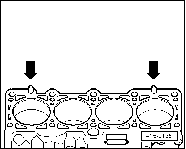
Remove new cylinder head gasket from packaging, just before installation.
t  Handle gasket extremely carefully. Damage to the silicone coating or the indented area will lead to leaks.
t  No oil or coolant must be allowed to remain in the blind holes for the cylinder head bolts in the cylinder block.
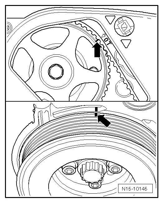
t  Locking fluid for hot working bolts → ETKA (Electronic parts catalogue)
  WARNING
The rotation of the engine must only take place on the crankshaft in the rotation direction of the engine (clockwise).
  Note
The engine should revolve around the central bolt of the crankshaft.
  A15-0764
–  Before fitting the cylinder head, set the camshaft at cylinder 1 TDC -upper arrow-.
–  Check again that the crankshaft is at cylinder 1 TDC -lower arrow-.
–  Fit the cylinder head gasket.
  N15-10145
t  Pay attention to centring pins in cylinder block -arrows-.
t  Observe correct installation position of the cylinder head gasket: The Part No. should be legible from inlet side.
–  Fit the cylinder head.
–  Insert cylinder head bolts and tighten by hand.
  A15-0135
–  Tighten the cylinder head in two stages, in the following tightening sequence:
–  Tighten with the torque wrench:
  A15-0767
stage:Tighten
1
–  Tighten to 40 Nm using a torque key.
2
–  Retighten with rigid spanner 90° (1/4 turn)
3
–  Retighten with rigid spanner 90° (1/4 turn)

  Note
Cylinder head bolts do not have to be torqued down again later after repair work.
–  Fitting notched belt and adjusting timing:
   removing and fitting; vehicles without separated notched belt guard → Chapter
   Removing and installing the toothed belt; vehicles without separated toothed belt guard → Chapter
–  Install cylinder head cover → Chapter.
–  Install poly V-belt → Chapter.
–  Electrical connections and routing → Current flow diagrams, Electrical fault finding and Fitting locations.
–  Remove the intake manifold → Chapter and the fuel rail → Chapter.
–  Connect battery → Electrical system; Rep. gr.27.
–  Checking oil level → Fig.
–  Fill up coolant → Chapter.
  Note
t  The drained coolant can only be reused if the cylinder head or the cylinder block have not been replaced.
t  Do not reuse the dirty coolant.
–  Read the fault memory and erase all recorded errors due to fitting → Chapter.
  Note
The readiness code must be generated if the fault memory has been erased → Vehicle diagnostic, testing and information system VAS 5051„Guided Functions“.
  WARNING
Do not use a charger as a starter aid! The control units of the vehicle may be damaged.
   

Engine lubrication > < Servicing valve gear