seat Workshop Repair Guides

SEAT Workshop Service and Repair Manuals

Parts of the exhaust system > < Servicing injection system
Removing and fitting exhaust manifold
  Note
Some of the components shown in the process are only fitted in vehicles with contamination phase EU4. This should be remembered when carrying out the work.
t  Removing → Anchor
t  Installing → Anchor
Special tools and workshop equipment required
   
t  Special wrench -U-40080-
  W00-2236
Removing
–  Remove central soundproofing -Anchorage points 1 ... 3-.
  Note
The vibration shock absorbing elements in the front exhaust pipe must not be bent more than 10° - otherwise they can be damaged.
  A10-1565
–  Remove securing nuts -arrows- for exhaust manifold to front exhaust pipe.
  N10-10085
–  Unbolt the exhaust system bracket -arrows-.
  A10-1632
–  Remove bolt -3-.
–  Loosen bolts -1- and -2- of the exhaust manifold bracket.
  A26-0712
–  Detach engine cover -arrows-.
  E10-10017
For engines with identification letters BLR and BVY
–  Remove the connectors -1- and -2- of the lambda probes in front of the catalytic converter of the support and disconnect them. (The number of connectors may vary depending on version).
  A10-1614
–  Disconnect the connector -2- of the exhaust gas recirculation valve with a potentiometer for exhaust gas recirculation (The hoses remain connected).
  Note
Shown in illustration with engine removed.
  E26-10013
–  Disconnect the exhaust gas recirculation pipe -1- from the exhaust manifold.
–  Disconnect the exhaust gas recirculation pipe -2- from the exhaust gas recirculation valve.
–  Remove the fastening from the exhaust gas recirculation pipe -3-.
  E26-10009
–  Undo the securing bolt -1-.
–  Disconnect the exhaust gas recirculation pipe -2- from the exhaust gas recirculation valve.
  A26-0713
–  Release the lambda probe cable from the brackets -arrow-.
–  Dismount the lambda probe before the catalytic converter -1-using the wrench -U-40080-.
  Note
The coolant hoses of the exhaust gas recirculation valve should be left connected.
  A26-0708
–  Remove the exhaust gas recirculation valve -1 ... 3- and lay aside.
For engine identification letters BLR.
–  Lay bare the lambda probe cable (in front of the catalytic converter), by removing the staples -4-
–  Remove the lambda probe cable guard -5-
  E26-10010
Continue for all engines
–  Remove the heat shield on the exhaust manifold, by undoing bolts -1- and removing the plate -arrows-
  A26-0711
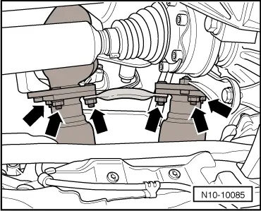
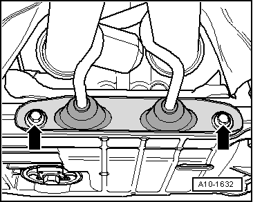
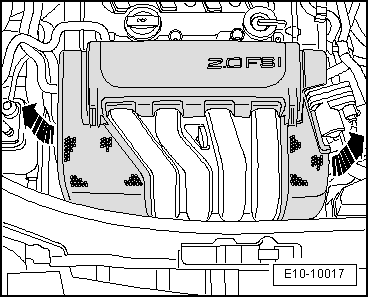
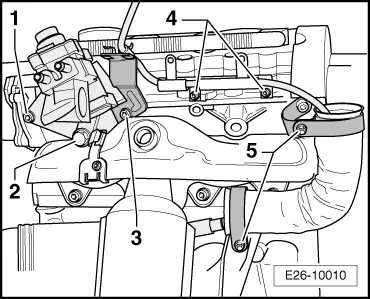
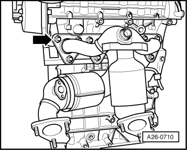
–  Dismount the fasteners on the exhaust manifold -arrow- and remove upwards.
Installing
Continue the installation in the reverse order of removal sequence, observing the following:
  Note
t  The screw thread on the new lambda probe is coated with a special paste; the paste must not get into the slots on the probe body
t  If a lambda probe is reused, apply paste to the bolts when warm; the paste must not get into the slots on the probe body. Locking fluid for hot working bolts → ETKA (Electronic parts catalogue)
t  
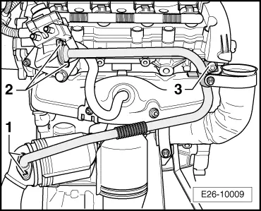
When assembling, the lambda probe cable must be fixed in its original position to avoid contact with the exhaust pipe.
t  Always replace self-locking nuts and bolts during assembly.
t  Renew all seals.
  A26-0710
–  Fit the heat shield -arrows-, bolt the plate with bracket to the exhaust manifold -1-
For engines with identification letters BLR and BVY
–  Fit the lambda probe. → Chapter.
  A26-0711

Parts of the exhaust system > < Servicing injection system