seat Workshop Repair Guides

SEAT Workshop Service and Repair Manuals

Exhaust system > < Lambda probes: removal and fitting
Procedure before opening the high pressure injection system. Warning!
The injection system is sub-divided into a high pressure system (max. approx. 110 bar) and a low pressure system (approx. 6 bar).
Prior to opening the high-pressure section, e.g. before removing the high-pressure pump, fuel rail, injectors, intake manifold flap motor for air-flow control or any other component located in the high-pressure zone of the injection system, the fuel pressure in the high-pressure section must be reduced to a residual pressure of approx. 8 bar. The appropriate procedure is described as follows.
Special tools and workshop equipment required
   
t  Central diagnosis -VAS 5051-
  W00-1236
t  Cable 3m. -VAS 5051/5A- or cable 5m. -VAS 5051/6A-
  W00-10194
Procedure
–  Remove the connector to the Solenoid valve 1 for active carbon filter (pulsed) -N80--1-
–  Start engine and run at idling speed.
  Note
next, select the control unit with the VAS 5051, then select display group 140 under the function „Read measured value block“.
  A24-0791
–  Connect the central diagnosis -VAS 5051- with the 3m. cable -VAS 5051/5A- or 5m. cable -VAS 5051/6A-.
–  Briefly press the key „Vehicle self diagnosis“.
  E90-10001
Indication on - VAS 5051 -:
–  Select vehicle system „01 - Engine electronics“ in menu -1-.
–  Wait until the following is displayed.
  A01-0120
Indication on - VAS 5051 -:
–  Select diagnosis function „08 - Read measured value block“ in menu -1-.
  A01-0122
Indication on - VAS 5051 -:
–  Key in display group 140 on keyboard -2- and confirm entry by briefly pressing key Q.
  A01-0130
Indication on - VAS 5051 -:
1 - Display field 1
2 - Display field 2 (specified pressure)
3 - Display field 3 (real pressure)
4 - Display field 4
5 - Display group X
Observe the display in display field 3. The value of the idle run shown in display field 3 is approx. 39 bar. The display shows the effective pressure (true pressure) in the fuel rail (common channel) generated by the high pressure pump. Display field 2 shows the pre-established pressure (specified pressure) The specified value should be the same as the true value.
  E01-10002
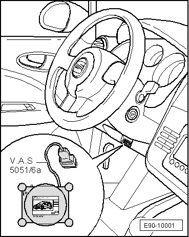
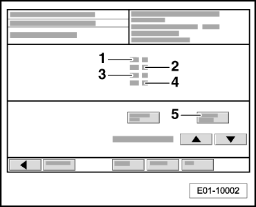
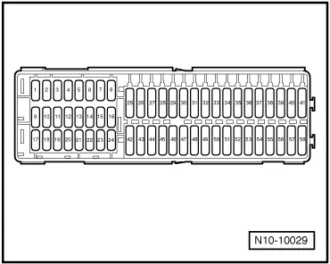
–  Remove fuses -4- and -43-(for the electric fuel pump control unit) in the fuse holder, below the instrument panel, left-hand side, and continue reading display field 3. The engine continues to run at idling speed.
The value shown in display field 3 drops rapidly as the mechanical high pressure pump is no longer fed by the electric fuel pump from the tank.
  Note
The display should not read below 6 bar; if so, the engine will stall (with the ensuing risk that the catalytic converter is damaged).
–  Switch off the ignition when the value displayed is approx. 8 bar.
The fuel rail is still full, however, the fuel is no longer under high pressure.
The components or pipes may now be disconnected. Put a clean cloth around the joints. Catch the fuel coming out.
–  Reinsert fuses 4 and 43 (for the fuel pump control unit).
  N20-10029
–  Fit the connector to the Solenoid valve 1 for active carbon filter (pulsed) -N80--1-
–  When the repair is finished, consult the fault memory of the engine control unit and erase it → Chapter.
  A24-0791

Exhaust system > < Lambda probes: removal and fitting