seat Workshop Repair Guides

SEAT Workshop Service and Repair Manuals

Lambda probes: removal and fitting > < Fuel supply parts: Removing and installing
Removing and installing engine control unit with locking device
t  Removing → Anchor
t  Installing → Anchor
Special tools and workshop equipment required
   
t  Electric cutter -SAT 1561-
t  Saw 102 -SAT 1561/9-
Removing
–  Before removing the engine control unit, the engine control unit identification and the engine control unit code must be consulted → Chapter.
–  Switch ignition OFF.
  W00-2720
–  Pull off rubber seal -2- on plenum chamber cover.
  E92-10015
–  Remove bolts -1-.
  E92-10014
–  Remove parting wall for plenum chamber.
  A10-1573
–  With the help of the electric knife -SAT 1561- and the saw 102 -SAT 1561/9-, make 2 parallel cuts -arrows- in the headless bolts.
–  Remove the bolts using pressure pliers or similar tool.
  N24-10096
–  Insert a screwdriver-A- between the control unit bracket and the locking device -arrow-.
  N24-10098
–  Turn the locking device outwards using the screwdriver -A-, and remove by pushing in the direction of the -arrow-.
  N24-10097
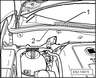
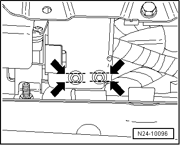
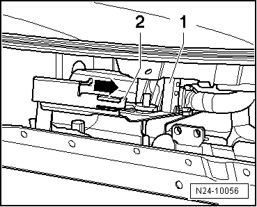
–  Unlock front connector -1- from the engine control unit and pull it off.
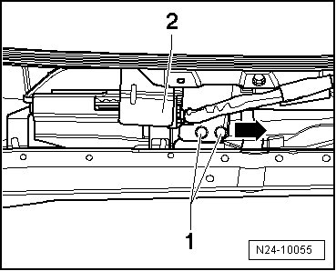
–  Carefully prise off the retaining plate safety clip -2- and next remove the engine control unit, pushing in the direction of the -arrow-.
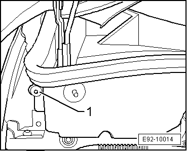
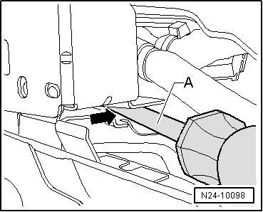
–  Now unlock the rear connector from engine control unit and pull it off.
Installing
Continue the installation in the reverse order of removal sequence, observing the following:
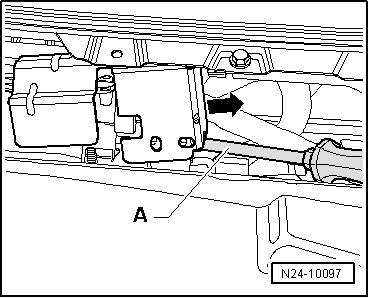
–  Attach the rear connector to the engine control unit and lock it.
  N24-10056
–  Place the retaining plate safety catch -2- in its original position and next slide the engine control unit in the opposite direction to that shown by the -arrow- on the retaining plate, until it is correctly fitted.
–  Connect the front connector to the engine control unit and lock.
–  Check the old coding and adjust the new control unit → Chapter.
  N24-10056
–  Place the locking device -2- on the control unit bracket.
–  Tighten the headless bolts -1- until the bolts break.
–  Fit the front panel on the plenum chamber → Bodywork - exterior installation work; Rep. gr.50.
–  Take vehicle for a test drive.
  N24-10055

Lambda probes: removal and fitting > < Fuel supply parts: Removing and installing