
Leon Mk1
|
|
|
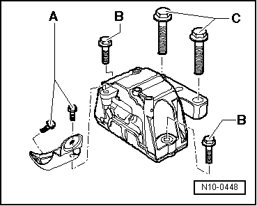
| -A-1) | 20 Nm + 90° (1/4 turn) |
| -B-1) | 40 Nm + 90° (1/4 turn) |
| -C-1) | 60 Nm + 90° (1/4 turn) |
| 1) Renew bolts | |
|
|
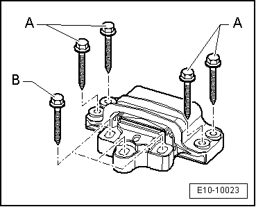
| -A-1) | 40 Nm + 90° (1/4 turn) |
| -B-1) | 60 Nm + 90° (1/4 turn) |
| 1) Renew bolts | |
|
|
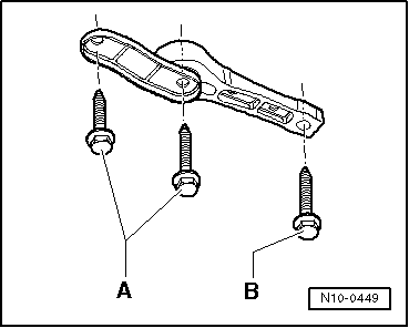
| -A-1) | 40 Nm + 90° (1/4 turn) |
| -B-1) | 100 Nm + 90° (1/4 turn) |
| 1) Renew bolts | |
|
|
|
|
|
|
|
|
|
 Note
Note
|
|
|
|
|
|
|
|
Note
|
|
|
|
|
|
Note
|
|
|
|