seat Workshop Repair Guides

SEAT Workshop Service and Repair Manuals

Notched belt drive components - assembly overview > < Bracket for auxiliary units: Removing and fitting (versions with small support)
Bracket for auxiliary units: Removing and fitting (versions with large support)
t  versions with large support: Removing → Anchor
t  versions with large support: Installing → Anchor
t  Specified torques → Anchor.
  Note
   
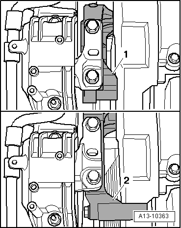
In vehicles with large engine support foot -2- it is necessary to dismount the engine support foot and suspend the engine to be able to dismount the ancillary brackets.
Consult the equivalence table for tools and equipment according to applicability among Seat / VW / Audi / Skoda → Chapter.
Special tools and workshop equipment required
  A13-10363
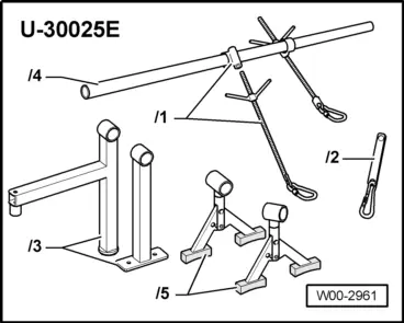
t  Socket -U 30025E-, see equivalent → Anchor
  W00-2961
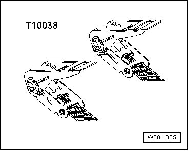
t  ♦ counterhold -T10038-, see equivalent → Anchor
Removing
  WARNING
Observe safety precautions when disconnecting the battery → Electrical system; Rep. Gr.27.
–  Remove engine cover .
–  Disconnect earth wire at battery with ignition switched off.
–  Remove Poly V-belt → Chapter
–  Remove the tension device for the Poly V-belt → Item
  W00-1005
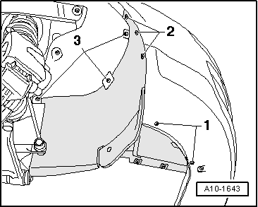
–  Remove the right soundproofing -Anchorage parts 1 ... 3-.
  A10-1643
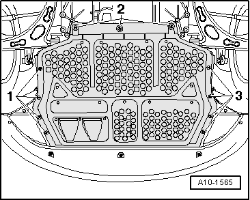
–  Remove centre noise insulation -mounting parts 1 ... 3-.
  A10-1565
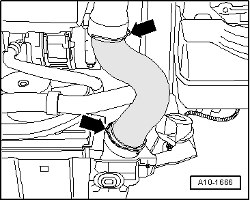
–  Remove the right hand side air conduit hose, to do this, lift the retainers slightly -arrows-.
  A10-1666
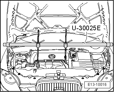
–  Fit the bracket -U-30025E- on the edge of the wing panels.
  Note
To secure the engine assembly with the support -U-30025E- this must be centred as much as possible with the symmetrical axis of the engine assembly.
–  Engage the trigger snaps of the spindles on the lifting eyes.
–  Pretension engine with both spindles equally, do not lift.
  E13-10016
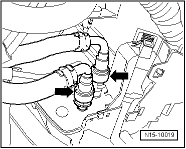
–  Release the couplings from the fuel lines -arrows-.
  Note
To do so, press the release tabs.
  N15-10019
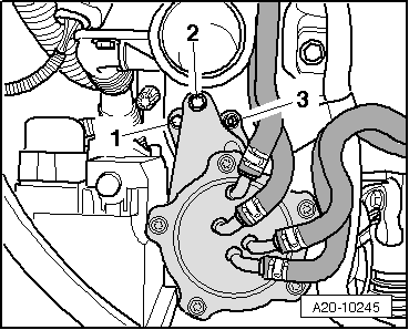
–  Loosen the bolt by one turn -1-.
–  Unscrew bolt -2- and nut -3-.
–  Leave the fuel filter to one side with the flexible hoses coupled.
–  Remove the filling mouth from the windscreen washer.
–  Remove the refrigerant element and leave it to one side (do not release the tubes).
  A20-10245
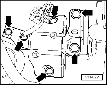
–  Remove the bolts securing the support assembly/engine support, support assembly/bodywork -arrows- and remove the whole support assembly.
  Note
t  The support unit should only be dismounted with the engine being held via the support -U-30025E-.
t  The engine mount should only be loosened once the support assembly has been removed.
  N13-0221
–  Raise the engine with the suspension tool -U-30025E- to extract the two upper bolts from the engine mount.
–  Lightly lower the engine with the suspension tool -U-30025E- to extract the lower bolt from the engine mount.
–  Remove the engine mount.
–  Remove the notched belt → Chapter.
  A13-10365
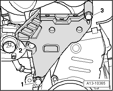
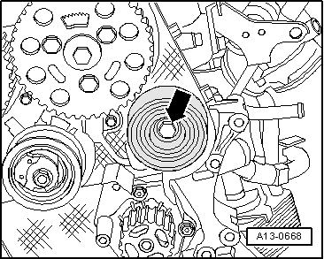
–  Unscrew the screw -arrow- with interior thread that holds the large engine support foot.
  A13-0668
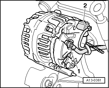
–  Unplug connector -2-.
–  Unbolt the electric cable -1- and the cable bracket.
  A13-0361
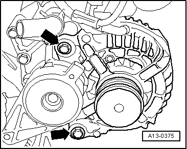
–  Screw out bolts -arrows- and remove alternator.
  WARNING
The air conditioning refrigerant circuit must not be opened.
  Note
To prevent damage to the air conditioning compressor and refrigerant pipes/hoses, ensure that the pipes and hoses are not stretched, kinked or bent.
  A13-0375
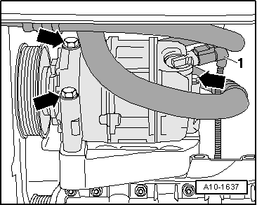
–  Disconnect electrical connection -1- for magnetic coupling on air conditioner compressor.
–  Remove compressor bolts -arrows-.
  A10-1637
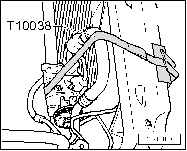
–  Suspend the air conditioner compressor above with refrigerant hoses still connected, securing it with the securing tool -T10038- to the lock carrier plate. Take special care not to damage the system.
  E10-10007
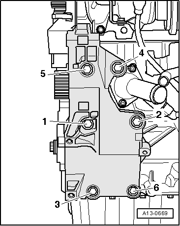
–  Remove bracket for ancillary units -bolts 1 … 6-.
Fitting
–  Installation is carried out in the reverse order.
–  Check whether dowel sleeves for aligning the ancillaries bracket are fitted in cylinder block and install sleeves if necessary.
–  Tighten the screws in the sequence-1 … 6-.
–  Fitting notched belt → Chapter.
–  Mount the engine support foot → Fig.
–  Install vibration damper → Chapter.
–  Install the air conditioner compressor → air conditioning system ; Rep. Gr.87.
–  Fit the alternator → Electrical system; Rep. Gr.27
–  Installing the Poly-V belt → Chapter.
–  Mount the right air conduit flexible tube.
–  Connect battery. Precautions → Electrical system; Rep. Gr.27.
Specified torques .
  A13-0669
ComponentNm
Bracket for auxiliary units on engine block45
Return roller to ancillaries bracket90 + 90° 1)2)
Engine support to bodywork50
Joint rib to engine support / bodywork20 + 90° 3)4)
l  1) Renew bolts
l  2) 90° equals a fourth of a turn.


Notched belt drive components - assembly overview > < Bracket for auxiliary units: Removing and fitting (versions with small support)