Leon Mk1
|

| 1 - | Cap |
| q | For vibration damper |
| 2 - | Special bolt - 10 Nm + 90° (1/4 turn) further |
| q | Replacement → Parts catalogue |
| 3 - | Vibration damper |
| q | For ribbed belt pulley |
| q | Can only be installed in one position. |
| q | removing and fitting → Chapter |
| 4 - | 10 Nm |
| q | Fit with locking fluid; locking fluid → Parts catalogue |
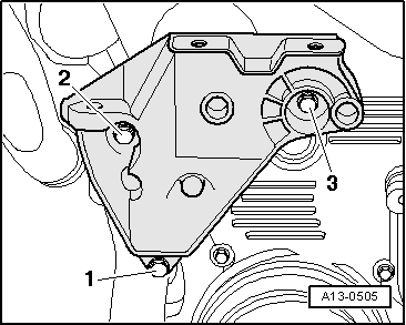
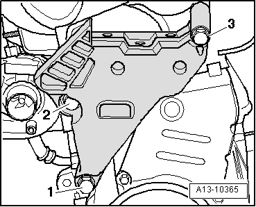
| 5 - | Screw for the engine support foot |
| q | Replace. |
| q | Tightening torque and succession order to tighten for the small engine foot support → Fig. |
| q | Tightening torque and succession order to tighten for the large engine foot support → Fig. |
| 6 - | Engine support |
| Different procedures: |
| q | Small engine support foot → Fig. |
| q | Large engine support foot → Fig. |
| 7 - | Upper protection element for the notched belt |
| q | When fitting, carefully hook on to the centre protection for the notched belt |
| 8 - | Notched belt guard - centre part |
| q | For removal, remove the notched belt upper protection and unscrew the Poly-V belt tensioning device |
| 9 - | Notched belt guard - lower part |
| 10 - | 10 Nm |
| q | Fit with locking fluid; locking fluid → Parts catalogue |
|
|
| 1. phase |
| ||
| 2. phase |
| ||
| 3. phase |
|
|
|
| 1. phase |
| ||
| 2. phase |
| ||
| 3. phase |
|
 Note
Note
|
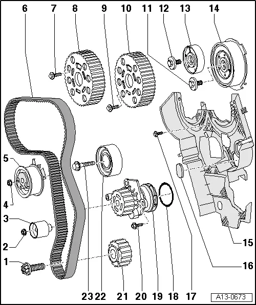
| 1 - | 120 Nm + 90° (1/4 turn) further |
| q | Replace. |
| q | Do not use oil |
| q | Use locking spanner -T20018B- to loosen and tighten → Chapter |
| 2 - | 20 Nm |
| 3 - | Idler wheel |
| 4 - | 20 Nm +45° (1/8 turn) |
| q | Use the correct tightening torque to avoid damages to the engine. |
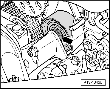
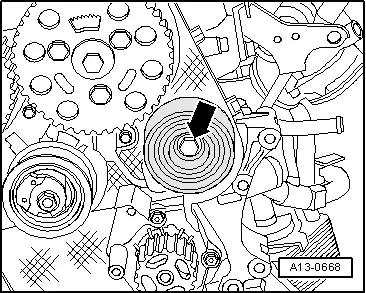
| 5 - | Tensioning roller |
| 6 - | Notched belt |
| q | Mark direction of rotation with chalk or felt pen before removing |
| q | Check for wear |
| q | Removing vehicles with small engine support → Chapter; vehicles with large engine support → Chapter |
| q | Fitting (adjusting the valve timing): vehicles with small engine support → Anchor; vehicles with large engine support → Anchor |
| 7 - | 25 Nm |
| 8 - | Camshaft wheels |
| q | For exhaust camshaft |
| q | Mark the installation position |
| 9 - | 25 Nm |
| 10 - | Camshaft wheels |
| q | for exhaust camshaft |
| 11 - | 100 Nm |
| q | Use retention tool -T10051- to loosen and tighten, see camshaft: removing and installing → Chapter |
| 12 - | 100 Nm |
| q | Use retention tool -T10051- to loosen and tighten, see camshaft: removing and installing → Chapter |
| 13 - | Hub |
| q | For exhaust camshaft |
| q | To remove, use puller -T10052A-. |
| q | Extract → Chapter |
| 14 - | Hub |
| q | for exhaust camshaft |
| q | With sender wheel for Hall sender -G40- |
| q | To remove, use puller -T10052A-. |
| q | Extract → Chapter |
| 15 - | Rear notched belt guard |
| 16 - | Rubber grommet |
| q | If this is damaged, replace it |
| 17 - | 10 Nm |
| q | Fit with locking fluid; locking fluid → Parts catalogue |
| 18 - | O-ring |
| q | Replace. |
| 19 - | Coolant pump |
| q | removing and fitting → Chapter |
| 20 - | 15 Nm |
| 21 - | Crankshaft notched belt wheel |
| q | There should be no oil on the contact surface between the notched belt wheel and the crankshaft |
| q | Fitting is only possible in one position |
| 22 - | Idler wheel |
| 23 - | Return roller screw |
| q | Replace. |
| q | There are different screws for vehicles with small or large engine support foot |
| q | Tightening torques: vehicles with small engine support → Fig.; vehicles with large engine support → Fig. |
|
|