
Leon Mk1
 Note
Note |
|
|
| Special tools and workshop equipment required |
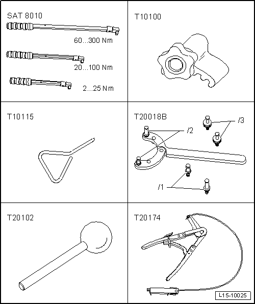
| t | Torque wrench -SAT 8010-, see equivalent → Anchor. |
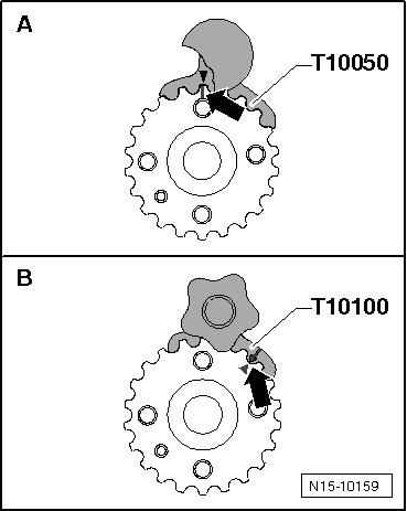
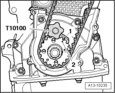
| t | Hose clamp -T10100-, see equivalent → Anchor |
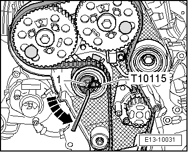
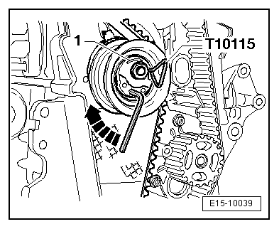
| t | Hose clamp -T10115-, see equivalent → Anchor |
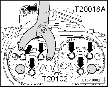
| t | Hose clamp -T20018B-, see equivalent → Anchor |
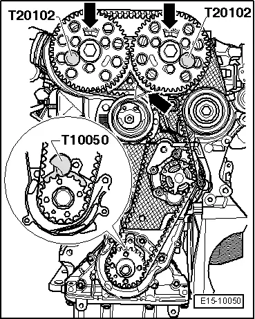
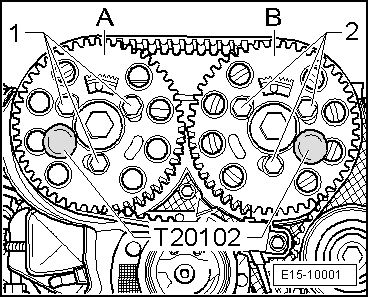
| t | Hose clamp -T20102-, see equivalent → Anchor |
| t | counterhold -T20174-, see equivalent → Anchor |
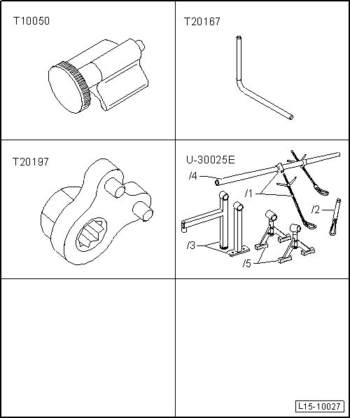
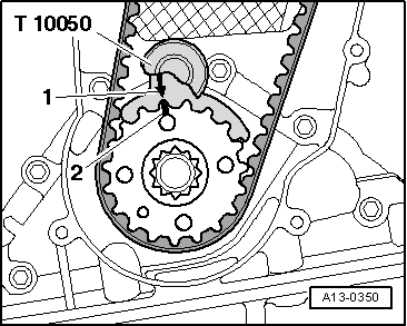
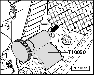
| t | Hose clamp -T10050-, see equivalent → Anchor |
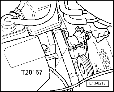
| t | Hose clamp -T20167-, see equivalent → Anchor |
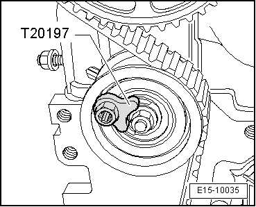
| t | Turning tool -T20197-, see equivalent → Anchor |
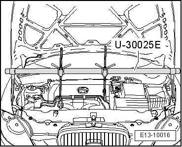
| t | Socket -U-30025E-, see equivalent → Anchor |
|
|
|
|
|
 WARNING
|
|
|
|
|
|
|
|
|
|
Note |
|
|
|
|
|
|
|
|
|
|
|
|
|
|
|
Note
|
|
Note
|
|
|
|
|
|
|
|
|
|
|
|
|
|
|
|
Note
|
|
|
|
Note
|
|
|
|
Note |
|
Note
|
|
Note |
|
Note
|
|
|
|
|
|
|
|
|
|
|
|
|
|
Note
Note |
|
|
|
|
|
|
|
|
|
|
|
|
|
Note
|
|
|
|
| Component | Nm | |
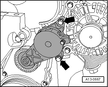
| Notched belt tensioning roller to cylinder head | 20 + 45° → Note | |
| Camshaft pinion to bin | 25 | |
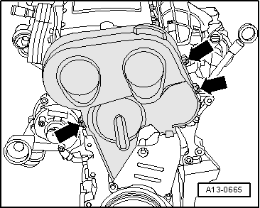
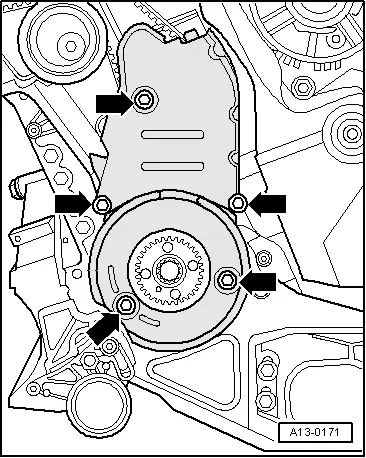
| Bottom section of notched belt guard to cylinder block | 10 → Note | |
| Centre section of notched belt guard to cylinder block | 10 → Note | |
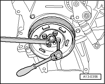
| Vibration damper to the crankshaft wheel | 10 + 90° → Note → Note | |
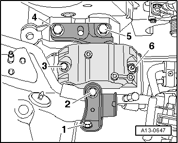
| Engine mount to the engine block | 40 Nm +1/2 turn further (180º) | |
| Engine console to body | 50 | |
| Engine mount to engine console | 40 + 90° → Note → Note | |
| Connection to engine console/body | 20 + 90° → Note → Note | |
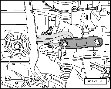
| Pendulum support to subframe | 100 + 90° → Note → Note | |
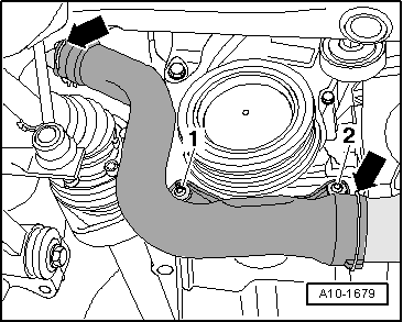
| Front supercharger air tube to the engine block | 22 | |
|